Hi
If the supply is only 450V, then you can use single 500V caps in each filter position instead of series caps. The latter divide to a lower value, ie, 220uF + 220uF = 110uF, the two 47s make only 223.5 ! The 500V caps will accommodate the turn on surge while the tubes warm up.
In the capacitive multiplier when used to support tubes, the input resistor feeding the multiplier cap must be a much lower value than what you are using. 10k is good, anything higher telescopes through to the amp as reduced transient response.
The filter cap should NOT have a resistor across it, otherwise you create a voltage divider that is unnecessary and creates excess heat in the mosfet.
The resistor in parallel with the mosfet G-S is not necessary either.
With 10k input, 1k max gate-stop, 22uF as the multiplier cap, and another 100uF on the output, you get about 50dB of hum quieting. The mosfet must be a large-package type (TO-3P or similar), preferably with low gate capacitance. 9V zeners seem margin as it can cause the mosfet to latch. You only need a single zener here. Remember: the mosfet has a reverse body-drain diode that protects it when the caps are discharging.

Any schematic ?
But If you use 10k on the input the mosfet will open too fast and will be high current to charge the capacitor after.
But If you use 10k on the input the mosfet will open too fast and will be high current to charge the capacitor after.
What's your opinions about high value capacitor after the mosfet?
Yesterday I have testet without capacitor after and looks OK at any frequency and power.
Yesterday I have testet without capacitor after and looks OK at any frequency and power.

Just a clarification: did you use the scheme on page 19 of the linked doc?Hello,
A few time ago I made a 40w Push-Pull amplifier with EL34 tubes, based on this description by Claus Byrith. : EL34 Push-Pull
Thanks!
How is your startup/shutdown process with the SS regulator? I am always afraid of transients, overcurrent charging caps and overvoltages at shutdown, clicks and pops on the speakers and the likes.
Yes, this is the schematic with a little modification. I use separate potentiometers for each EL34 biasing. And the NFB is a little less.Just a clarification: did you use the scheme on page 19 of the linked doc?
Thanks!
Right now I have no any power regulator. Is just like on the original description, but I have 4x220uF. page 20, with the simplest version with no choke.
Last edited by a moderator:
It’s not about power regulation. Most likely what you are seeing is cathode hum induced from the heater supply at the input stage.
Hello, as described no hum, the amplifier is totally quiet. And if I add a capacitor multiplier the spectrum became clean.
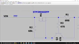
I wanted to understand the suggestions from nauta better, so here is a full circuit. I pulsed the current draw to simulate transients, when the resistor across the cap is remove the voltage varies a lot more during the pulses. I upped the zener voltage and used the body zener in place of the second one. The mosfet dissipates a few watts after startup. I'm open to suggestions on improving it - the previous circuit has been working for several years in an amp but that doesn't mean it's right.


Attachments
Today you can get big electrolytics in a small form factor. So unless you have a tube rectifier why have the mosfet hum remover.
You can add a current limit with a NPN BC547 placed across the gate source and a series resistor in the source to drop .65V at the current limit. A small series resistor in the base just to protect the NPN.
You can add a current limit with a NPN BC547 placed across the gate source and a series resistor in the source to drop .65V at the current limit. A small series resistor in the base just to protect the NPN.
Hi
The circuit in your sim has too small of an input filter cap. This is the first point in the circuit where we can eliminate a huge amount of hum yet many manufacturers and designers drop the ball - then hobbyists copy the error and wonder why the amp hums. In a tube power amp, this really must be 220uF or more. As others pointed out, modern caps are tiny AND the legacy cap values are based on the use of a tube rectifier with limited cathode emission ratings.
The purpose of the active hum filter is right in its name. It is not a voltage regulator. In a push pull tube amp there is no need to regulate B+, just to keep it clean especially for triode or ultralinear operation. With a clean supply node, all three operating modes for a tetrode - pentode will have the same low noise floor.
The 20M across the gate filter should be removed. Again, it interferes with the hum rejection.
A current clamp for the mosfet is an intuitive thing to add except that it ruins the output impedance vs frequency. Same goes for not having an output filter cap. You want this node to be at AC ground and for transient currents to go through that cap - which is placed locally to the output stage - not through the mosfet.
Remember that several things work together to keep the output signal clean. The push-pull amp with its output stage HUM-BALANCED (not DC balanced) will reject supply noise over its entire output range. The PA NFB loop works to cancel hum, as well. Proper wiring and grounding reduce hum. A DC standoff for the heaters reduces hum. The active hum filter will help all of this with minimal dissipation.
The PSU has its inherent regulation, mostly based on the size of the PT, but then specifically on the plate winding on the PT. Unless this is massively over-rated, regulation of this winding could be 10-20%. This does not matter for a hifi provided that the full-load voltage is adequate to produce the output power goal. At full sag, the next thing is clipping, which you never want to experience with hifi speakers.
Last edited:
Hi,
I did some measurments today using this schematic but with no capacitor on the output, just one 0.47uF foil capacitor on the PCB, close to the EL34 tubes.
The hum with no mosfet filter is about 8Vpp, is not audible at all on the speaker. With filter is about 100mV. The spectrum is much better with mosfet filter. (it was showed before)
Regards to the output impedance I measured about 0.9 Ohms with no mosfet filter, and with mosfet I see the same at 100Hz, 1kHz, just above 10Khz I see a slightly increase with about 0.1 Ohm.
The output impedance has little dependency on the power supply impedance, as the former is differential and the latter common mode. If your happy with your mosfet great. The only thing I would say is 1M is quite a high impedance to drive the power mosfet, and the zener may leak a bit.
I have 330K on gate. With 1M was too much voltage drop on the mosfet. It was about 25...30V. With 330K is just 12....15V. Exactly enough to compensate the 8Vpp ripple.
OK but you may find that changes with temperature. Better to define the drop with a potential divider with a high value resistor to ground and use lower value resistors.
Hi
In real amplifiers, there is no need to have a fixed voltage drop across the hum filter. That 8Vpp is only at full load. The hum filter will follow the loaded voltage up and down while reducing how much hum gets to the amplifier.
If you listen to compressed music, the supply will sag and everything adjusts to the reduced B+. Hum is minimal.
if you listen to more dynamic music, the hum-balanced amplifier will accommodate any short-term rise in hum from the active filter as it follows the voltages up and down. Here is where a properly "huge" main filter is beneficial AND why you need the high-value output filter. Transient voltage loadings will cause transient hum increase on B+, but the high-value caps help absorb the differences and the hum-balanced amp output will be quiet all the time.
You can do a load test on the amp to determine the minimum main filter value that provides a clean output. Use a resistive load for the amp, hook up your scope to the speaker output and sweep the input level up until clipping with a sine wave input. If the clipped output is clean and square, then the filter value is good. If there are spikes into the square wave, this is ripple modulating the signal. Add a filter in parallel and retry until there is a clean output.
It can be surprising how low the minimum filter can be. In a 160W amp, the main filter was increased in 47uF increments. Somewhere between 3 caps and four caps the output became clean. I did not bother to zoom in on the exact value, so I just used 4x47uF = 188uF total. This was using Solen PP caps. A choke and 22uF filtered the screens throughout the test.
Once you have the main filter cap sorted, you can add the hum filter to allow triode and UL operation at extremely low-noise.
- Home
- Amplifiers
- Tubes / Valves
- EL34 push-pull