@Francois G, the two boards pictured are the heater supply boards I linked in my prior post. These are it - https://www.diyaudio.com/community/...pplies-mic5156-based-tube-amp-upgrade.382265/
Thanks. I see, then Zintolo is likely suggesting the substitution of a choke for R27 on each amplifier board.
Hmm, ok. I see that is a well recommended upgrade. I see you yourself recommended the Hammond 159T over the 159V if using EL34 tubes. Might look to putting in an order for a pair of those. Thanks for the advice.
A CLC filters the ripple better than a CRC, but it's one of the most expensive upgrades that can be done on this amp and requires space to be installed too.Zintolo is likely suggesting the substitution of a choke for R27
I would go through steps to see what makes it better, what worse, what has no impact.
Hmm, ok. I see that is a well recommended upgrade. I see you yourself recommended the Hammond 159T over the 159V if using EL34.
I don’t remember the context of that recommendation, but if you are able to it might be useful to run PSUD2 to see the effects of choke choice. https://groups.io/g/duncanampspsud
Each PCB will on average need no more than 100 ma in choke capacity. So, even a Hammond 159T is overkill wrt current capability, and as @zintolo said, choke are relatively expensive. The trade-off is the resistance in chokes of lower current capacity that will result in lower B+.
If you what to go with a choke in each PCB in this context, my choice would probably be a choke with >125 ma and inductance > 1.5 H and check the B+ drop due to the choke resistance.
Thanks @zintolo & @Francois G, for now will perform zintolo's mods, then go from there. I am still getting a bit of hum, maybe tube rush.. when ears next to speaker. It's hard to make any serious determination about the hum with amp sitting as it is currently. The tubes I have also did redplate a few times as I was going through troubleshooting, not sure if hum is consequence of that. I think more likely 60hz hum. Damaged tubes in my experience are more noisy, where this is a constant low hz hum, but quiet.
Did all the mods as suggested by @zintolo. It was a bit hard to make any real comparisons along the way. Installing new components took me some time. I wouldn't trust myself with before/after comparisons, would think others to trust them less 😀. I did listen along the way on my test speakers, and it did sound better as I went along the way. More of everything. One question regarding this topic, is socketing resistors generally not recommended for a circuit such as this?
I am also fighting the hum and chasing balancing one of the 12AX7's with R5, it's drifting much more than its counterpart. They're cheapest Chinese tubes I could fine for sake of testing, looking to pickup another set now. The hum issue I think is related to biasing, though adjusting R5 does modulate the hum. At one point I found one board to hum when V3 was same as V2, but when set about 40mv lower it would be quiet - like 530mv for V2, 490 for V2. Swapping V3 and V2 tubes seemed to get rid of the issue, but still some hum on both channels when I put ear next to drivers. The seller of the EL34 quad is going to send me a replacement tube..
Just wanted to report back, sounding good but need to get in new set of 12AX7's, see how biasing affects sound.
I'm happy you liked them. I liked them too.Did all the mods as suggested by @zintolo and it did sound better as I went along the way. More of everything.
What do you mean by "socketing resistors"? Which resistors?One question regarding this topic, is socketing resistors generally not recommended for a circuit such as this?
Most probably with a reliable set of tubes everything will be set.Just wanted to report back, sounding good but need to get in new set of 12AX7's, see how biasing affects sound.
The one's mentioned in your recommendation post here, thinking being it would allow one to quickly swap parts to see what changes result.What do you mean by "socketing resistors"? Which resistors?
Most probably with a reliable set of tubes everything will be set.
I'm hoping to make a purchase of a NOS set today! One additional question I forgot to ask. The values for C1 and C2 in relation to ground are 220V on both boards. Is this an acceptable value? Build guide says 150V-200V. R18 resistor to 1Kohm had largest effect on this, before swapping to 1K it was at about 150V. Any thoughts on this? Would it worth trying something like 800ohm for R18?
I'm happy you liked them. I liked them too.
Yes! Thanks again for your time, knowledge, and especially your patience!
Been a while since I've been here. I made two of the BH's about 5 years ago and another friend also made one. All 3 of these use the KT88 tubes.
This is probably all fixed with the heater supply changes referenced in the past few posts here and maybe other had this problem and found fixes. But it's too long of a thread to go find what others have done. I thought I would just come back here and drop a note of the problems we had and how we resolved them.
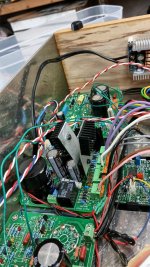
We had problems recently with all 3 amps, after years of operation. The problem is with the tube heater supply section of the power supply board. The KBU1004 rectifier gets so hot that it eventually caused the solder joints for the rectifier to fail, which lost heater power.
The rectifier is rated for a max of 10 amps. With 4 KT88s and two 12AX7s we're still under that threshold but pushing it pretty hard at close to 8 amps. And the rectifier specs say the 10 amps is with a heatsink, which the version 1.5 boards we used did not have. They also didn't have any space for a heatshink.
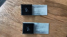
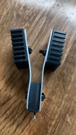
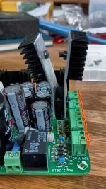
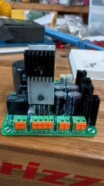
We purchased new rectifiers, and left the legs long on them so we could mount them up high, then made a heatsink to attach to them. Here's a few pictures that describes what we did.
I hope there are many here enjoying the BH. This is the first problem we've had with them, so they have been pretty reliable. I see some familiar names here, glad you guys are still working to make it better!
There are a few things on this version that could be better in addition to schematically (which we did make a few mods). One thing is just the connectors, especially on the power supply board but also on the channel boards as well. The connectors in our BOMs were marginal in terms of voltage ratings and how robust they were. Especially the HV connectors. That thing has the leads so close together it makes me nervous, with 400+ vdc on those connectors one little mistake can make a big bang. I would even be in favor of some more widely spaced solder connections, but the mechanical connector is convenient. I just wish it was rated more conservatively and a bit more robust. Spacing, heat dissipation, better connectors, and things like that should be considered if looking at an updated version.
Another issue we had was with the circuit boards. They are nice boards, but they have traces on both sides of very thick boards. The way these are designed makes it really difficult to extract and replace parts without messing up traces on the boards. After a few mods, I screwed up a channel board to badly I purchased a new board and re-did the entire board. For an updated version, better boards would also be nice.
Just a couple of thoughts, we'll probably never build another one, so it's all just for the new builders to consider.
This is probably all fixed with the heater supply changes referenced in the past few posts here and maybe other had this problem and found fixes. But it's too long of a thread to go find what others have done. I thought I would just come back here and drop a note of the problems we had and how we resolved them.
We had problems recently with all 3 amps, after years of operation. The problem is with the tube heater supply section of the power supply board. The KBU1004 rectifier gets so hot that it eventually caused the solder joints for the rectifier to fail, which lost heater power.
The rectifier is rated for a max of 10 amps. With 4 KT88s and two 12AX7s we're still under that threshold but pushing it pretty hard at close to 8 amps. And the rectifier specs say the 10 amps is with a heatsink, which the version 1.5 boards we used did not have. They also didn't have any space for a heatshink.
We purchased new rectifiers, and left the legs long on them so we could mount them up high, then made a heatsink to attach to them. Here's a few pictures that describes what we did.


I hope there are many here enjoying the BH. This is the first problem we've had with them, so they have been pretty reliable. I see some familiar names here, glad you guys are still working to make it better!
There are a few things on this version that could be better in addition to schematically (which we did make a few mods). One thing is just the connectors, especially on the power supply board but also on the channel boards as well. The connectors in our BOMs were marginal in terms of voltage ratings and how robust they were. Especially the HV connectors. That thing has the leads so close together it makes me nervous, with 400+ vdc on those connectors one little mistake can make a big bang. I would even be in favor of some more widely spaced solder connections, but the mechanical connector is convenient. I just wish it was rated more conservatively and a bit more robust. Spacing, heat dissipation, better connectors, and things like that should be considered if looking at an updated version.
Another issue we had was with the circuit boards. They are nice boards, but they have traces on both sides of very thick boards. The way these are designed makes it really difficult to extract and replace parts without messing up traces on the boards. After a few mods, I screwed up a channel board to badly I purchased a new board and re-did the entire board. For an updated version, better boards would also be nice.
Just a couple of thoughts, we'll probably never build another one, so it's all just for the new builders to consider.
Last edited:
Hi gbowling,
Use separate heater supplies. The same winding if the transformer is happy, but teh rectifier forward should be divided. Heat (current) is your enemy, and that goes for ripple current in your heater filter capacitors.
Use separate heater supplies. The same winding if the transformer is happy, but teh rectifier forward should be divided. Heat (current) is your enemy, and that goes for ripple current in your heater filter capacitors.
Yea, that's a good idea @anatech but that wasn't the way the v1.5 power supply board was designed. The version we built had the output of the PSU board feeding a buck converter that supplied the heaters.
Sure, it can be modified, but for now we're going to see if the homemade heatsink will work. I suspect it will, it operated for 5 years, used almost daily without anything before it failed. Raising the rectifier off the board and adding the heatsink should provide considerable cooling over the way it's been.
Sure, it can be modified, but for now we're going to see if the homemade heatsink will work. I suspect it will, it operated for 5 years, used almost daily without anything before it failed. Raising the rectifier off the board and adding the heatsink should provide considerable cooling over the way it's been.
I'm looking at it from a service standpoint. If the rectifier runs that hot, a heat sink merely lowers the temperature a little. You really want to drop it a lot to be reliable. This will also greatly extend the life of the filter caps.
The power supply PCB was not suitable for KT88 output heaters, or even EL34 heaters. I split mine running 6L6GCs, two windings in the power transformer to reduce temperatures and IR losses. It can handle EL34s no problem. Also, no need to run the outputs on DC, there isn't enough gain to be worried about hum. Going AC right there solves a lot of grief.
The power supply PCB was not suitable for KT88 output heaters, or even EL34 heaters. I split mine running 6L6GCs, two windings in the power transformer to reduce temperatures and IR losses. It can handle EL34s no problem. Also, no need to run the outputs on DC, there isn't enough gain to be worried about hum. Going AC right there solves a lot of grief.
Also, no need to run the outputs on DC, there isn't enough gain to be worried about hum. Going AC right there solves a lot of grief.
That was my solution. AC on the power tubes, DC on the 12AX7. Requires a little Dremel tool work. I believe @zintolo doesn’t use DC at all, apparently with great results.
@Francois G
I elevate AC heaters by 40-50 Vdc and I’m fine with them.
I also use quasimodo method for the power transformer: https://www.diyaudio.com/community/...rmer-snubber-using-quasimodo-test-jig.243100/
I elevate AC heaters by 40-50 Vdc and I’m fine with them.
I also use quasimodo method for the power transformer: https://www.diyaudio.com/community/...rmer-snubber-using-quasimodo-test-jig.243100/
What B+, Raa and UL% are you using?I made two of the BH's about 5 years ago and another friend also made one. All 3 of these use the KT88 tubes.
Are you dropping screen voltage with a zener?
I use that solution in guitar amps, where signal passes through 5-6 triodes in series before reaching output tubes.That was my solution. AC on the power tubes, DC on the 12AX7.
- Home
- Amplifiers
- Tubes / Valves
- EL34 Baby Huey Amplifier