
Ok, the two are matched with 680ohm at R18. Have them wired up to a pair of test speakers and playing music. Sounds good.
Measurements not changed since last report.
Measurements not changed since last report.
R1 has 12kohm resistor installed, per BOM.Perfect. Tell me voltages at C10 and C11.
Have you installed R1?
C10 measures 67V across, C11 measuring 76V across.
Ok, I suggest you different steps.
1: substitute R17 with a red led like LED1, same orientation like LED1, and R16 with 33k.
Listen to the sound. Focus on mids and highs at medium volume.
2: remove R1 and C3 if you have it.
Listen to the sound. Focus on low and then high volume.
3: substitute R33 and R38 with 150 Ohm.
Listen to sound. Focus on medium and high volume.
4: Substitute R18 with 1k. Measure voltage on 12ax7 cathodes.
Listen to sound. Focus on low and high volume.
PS
I'd also raise R14 and R15 to 1k as suggested on datasheets for EL34 in UL.
This is for the safety of screen grids if amp is often pushed.
thanks @zintolo, will get an order going 🙂. Voltage at C1/G and C2/G are cathodes voltages, yes? One concern I have is balancing these two with R5, the value is very jumpy. Varying 100-200mv around 0. Also I set it after let's say 2 minutes, after 10 minutes it has drifted some, the same after 1hr. Is there anything you might think of which might alleviate this? Anything I might include in this next order..
Voltage at C1/G and C2/G are cathodes voltages, yes?
No @arteom, C1/G and C2/G are the plate (anode) voltages. You want to adjust them as close to zero as is possible on the volt scale of your meter (NOT the mV scale which could jump around a bit). Exercise your R5 wiper a few time to make sure it is tracking as well as possible.
Listen to the sound. Focus on mids and highs at medium volume.
Hi Roberto. What exactly are you listening for in these steps? What do you do after you listened?
Ciao Francois, I prefer not to write it here now to avoid any bias on impressions. I can PM you if you prefer.Hi Roberto. What exactly are you listening for in these steps? What do you do after you listened?
No @arteom, C1/G and C2/G are the plate (anode) voltages. You want to adjust them as close to zero as is possible on the volt scale of your meter (NOT the mV scale which could jump around a bit). Exercise your R5 wiper a few time to make sure it is tracking as well as possible.
Ah, thanks Francois. I misread the schematic. Pins 3&8 are cathode, where pins 1&6 are connected to C1&C2.
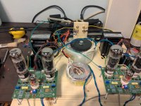
I don't know how much I or anyone else might trust my ears. Right now there is a very low frequency hum present in the speakers. I attribute it to my temporary placement. The Boards are standing on 50mm M3 screws. I do have a small metal backpanel from another chassis which is hosting IEC and RCA inputs. The HV transformer has a shield wire which is grounded to that, I also ran a wire each from this backpanel to each board, hooking to one of its four legs. Otherwise everything is just sitting on a piece of MDF..
Attachments
No @arteom, C1/G and C2/G are the plate (anode) voltages. You want to adjust them as close to zero as is possible on the volt scale of your meter (NOT the mV scale which could jump around a bit). Exercise your R5 wiper a few time to make sure it is tracking as well as possible.
Just to be clearer. It is the difference between the two plate voltages (as measured at C1 and C2) that you want to adjust to zero. You mentioned you measured C1/G at 152 Vdc, but C2/G is much more and can’t be adjusted adequately by R5. (There is of course a problem! Have you checked the resistance values of R8 and R10?) Both plate voltages to grounds should be about the same when adjusted by R5, and between 150-200Vdc in value (as you noted depending on the supply voltages you use)
Hi Francois,Both plate voltages to grounds should be about the same when adjusted by R5, and between 150-200Vdc in value (as you noted depending on the supply voltages you use)
At this point I'm getting 136V on one of my two board and 140V on the other. Am able to get R5 around 200mv of zero, but it fluctuates up and down. I did try what you mentioned with turning R5 left and right many times, but had no effect.
R8 is 220k. What is weird about R10 is it is a 47k resistor, but when it measure lower when installed on the pcb - 30k. Same R9 and R13.
I am using a 275V HV transformer and 58V transformer for bias.
It's 138V +-1,4%. That's reasonable. Not optimal but reasonable.I'm getting 136V on one of my two board and 140V on the other
Did very carefully move the build to my main system to test on proper speakers. It sounds really good, and no hum!! Great sense of dynamics and imaging. Have put in an order for parts needed to perform @zintolo mods 🙂.

@zintolo - I was wondering if we should have a separate thread to capture your improvements to the basic design? It becomes increasingly hard to entice new builders of the amplifier because there is a lot of knowledge spread over an even greater number of posts. I remember having to do a lot of research to get the power supply board working.
Now that there is so much collective experience of this build, should be fairly easy to gather the baseline and start to prompt for suggestions for a new revision.
I made some suggestions for a change to the PCB because I struggled with changing a coupling capacitor. A Tubelab board is bullet-proof, but it was tricky to replace a Russian teflon capacitor because the hole was so tight on the lead.
Also, I am not sure that rectifying the heaters is worthwhile. If the heaters are not rectified, then that part of the PSU board could be used to elevate them. I was also wondering if there is a way to optimise the grounding, feels like there are a lot of connections to ground from 3 different boards.
Last edited:
@OldHector Sure I can!
I already did it for the EL84 version and I’ll be happy to do the same for EL34.
I’m also going to build a 7591 version in two monoblocks for a friend of mine. It’s a very nice tube to work with!
I already did it for the EL84 version and I’ll be happy to do the same for EL34.
I’m also going to build a 7591 version in two monoblocks for a friend of mine. It’s a very nice tube to work with!
@zintolo, the parts I have in use are AS-3T275 - 300VA 275V Tube Transformer, this one for bias voltage AU-0558 50VA 58V / 116V, Hammond 1650N Output Transformers. A pair of these 6.3VAC to 6.3VDC LDO supplies MIC5156 fed from HV 6.3VAC secondaries for the heaters. Besides that a pair of the original boards (with onboard PS), currently stock. Maybe chokes you are referring to are one's on the V2 power supply board? Or I might be very well missing something, as I am sure I am missing a lot 🙃.
Looking at the photo in post 1654 it appears that you are using two power supply boards, one for each amplifier board. Is that correct? What power supply boards are they? There is room for a choke in BH power supply PCB (between the large cap and the relay), or on each original PCB in lieu of R27. Personally, I would not have used two power supply PCBs (as cost saving) but since you have them I assume you are building two mono amps with only sharing the AC transformers. If that is the case you will need a choke for each power supply.
- Home
- Amplifiers
- Tubes / Valves
- EL34 Baby Huey Amplifier