Cheers for the recommendation of Sketchup! It was exactly what I was looking for in terns of quick drawings.
I did a mock up of the setup that I was considering using the sub in:
For comparisons sake here is a photo of my current setup with my first recently finished DIY speakers. It's changing a lot currently as I'm working on an amp based around an audiosector LM3875 kit, wall mounting the TV and organising the components on top of the cabinet.
How well would an arrangement like that with the U-shaped pipe work? What would the effect be of stacking two U-shapes on top of each other (with the drivers at one side or on opposite sides)?
Thanks for all the feedback so far guys!
I did a mock up of the setup that I was considering using the sub in:
An externally hosted image should be here but it was not working when we last tested it.
For comparisons sake here is a photo of my current setup with my first recently finished DIY speakers. It's changing a lot currently as I'm working on an amp based around an audiosector LM3875 kit, wall mounting the TV and organising the components on top of the cabinet.
An externally hosted image should be here but it was not working when we last tested it.
How well would an arrangement like that with the U-shaped pipe work? What would the effect be of stacking two U-shapes on top of each other (with the drivers at one side or on opposite sides)?
Thanks for all the feedback so far guys!
Hi Guys,
Great work on the sketch Steve! It's nice to be able to visualize what your final goal is.
That Visaton driver has a low Qts, so you're going to want to tune a little higher than the driver Fs. I'd suggest either 25 or 30 Hz. As a benefit, you'll be able to use a much smaller diameter tube than a higher Qts driver would allow for. If you're willing to try and taper the tube, you can drastically shorten your line. There's no scale in the drawing you made, so could you let us know what the length of the pipe turned out to be in your sketch? I'm guessing between 6 and 7 feet from the scale in the picture.
Low Qts drivers produce a saddle shaped response with a peak at the tuning frequency, and a peak at the next system resonance. If you tune a low Qts driver with an Fs of 30Hz to exactly 30Hz, then you'll get a peak at the tuning frequency (30Hz) followed by a saddle with another peak at 90Hz.
Tuning a little higher than the Fs of the driver helps to mitigate the peaks, and so does stuffing. Tapering the tube also helps. A careful combination of all these will produce a very flat response with no peaking in the usable band.
I'll model that driver tonight, and we'll see what works best.
Nelson,
Could you elaborate on your reason for not wanting the exit of the pipe near the driver? My understanding is that the output of the terminus and the driver are in phase, and combine to generate the desired output. Take a look at the last figure on page 23 of the following paper:
http://www.quarter-wave.com/TLs/Alignment_Tables.pdf
The blue trace is the pipe output, and the red trace is the driver output. The figure directly above is the combined farfield output. Wouldn't having the end of the pipe and the driver in close proximity help to create the desired combined output much sooner, and at a much more even level throughout the room? Having them in drastically different locations (e.g. ceiling and floor) means that you'll have the red trace response on the floor, and the blue trace on the ceiling, and some uneven combination of the two at various spots in the room.
If you only have one pipe, it might be beneficial to excite the room at different locations (the end of the line and the driver far apart), but with two pipes, wouldn't it be better to have the exit of the line near the driver, and then have two different pipes at different locations?
I could be completely wrong, but that's just my understanding of it.
Cheers,
Owen
opc said:As a benefit, you'll be able to use a much smaller diameter tube than a higher Qts driver would allow for.
Without also knowing Vas this is not true.
dave
From MJK's Alignment Tables:
All I meant was that "in general" lower Qts drivers tend to require less line area.
Cheers,
Owen
"As the Qts of the driver increases so does the size of the enclosure. This was somewhat of a surprise to me and provides some interesting options for smaller transmission line systems using low Qts drivers."
All I meant was that "in general" lower Qts drivers tend to require less line area.
Cheers,
Owen
opc said:Take a look at the last figure on page 23 of the following paper:
http://www.quarter-wave.com/TLs/Alignment_Tables.pdf
The blue trace is the pipe output, and the red trace is the driver output. The figure directly above is the combined farfield output. Wouldn't having the end of the pipe and the driver in close proximity help to create the desired combined output much sooner, and at a much more even level throughout the room? Having them in drastically different locations (e.g. ceiling and floor) means that you'll have the red trace response on the floor, and the blue trace on the ceiling, and some uneven combination of the two at various spots in the room.
If you only have one pipe, it might be beneficial to excite the room at different locations (the end of the line and the driver far apart), but with two pipes, wouldn't it be better to have the exit of the line near the driver, and then have two different pipes at different locations?
I would not assume that the sum of these in close proximity to each other
would result in flat response. Unfortunately it does not look like Martin
addressed this issue, or if he has, I have not seen it.
I speak just from general experience, having built many transmission lines
long (mostly at ESS) before there was good software. The successful
ones seem to consistently put some distance between the driver and
the terminus, and so it has become a rule of thumb.
😎
Nelson,
Thanks for clarifying your points on the terminus location. I guess someone would have to build two identical pipes, one with the terminus near the driver, and one with it farther away, to really measure exactly what was going on. I'll fire an email off to Martin to see if he has any experience with it.
Steve,
I was wrong about that Visaton driver being suitable for a TL. I glanced at it quickly, and didn't realize it had such a low BL. It requires huge amounts of line area (a 21" diameter pipe for a taper of 1) as a result.
If I were you, I would keep looking for something a little better suited. The Eminence Lab12 aligns pretty nicely in a 12" tube that tapers at a 0.333 ratio. It would only have to be about 9 feet long for a tuning of 25Hz. It's a little more expensive than the Visaton, but not much.
http://www.parts-express.com/pe/showdetl.cfm?Partnumber=290-570
What types of drivers are easy for you to get over there?
Cheers,
Owen
Hi,
The length of the pip in the model is 2.5m across with .5m extrusions toward the front for 3.5m in total - approximately the correct length when the driver is modelled with Martin's tables. The diameter of the tube is also to scale at 480mm. So it's a size that I could live with, with the visaton driver, but as you say - it's probably better looking for something better suited.
The Eminence looks good, and it isn't too much more expensive than the Visaton. However, will it go all the way down to 20Hz?
Also - the range of drivers I've been able to find for sale, particularly where I live is fairly limited.
http://soundlabsgroup.com.au/
http://www.essentialaudio.com.au/
Those should give you an idea.
Thanks,
Steve.
How does this driver look?
http://www.parts-express.com/pe/pshowdetl.cfm?&DID=7&Partnumber=295-190&ctab=1#Tabs
Steve.
http://www.parts-express.com/pe/pshowdetl.cfm?&DID=7&Partnumber=295-190&ctab=1#Tabs
Steve.
mrevie said:How does this driver look?
Qts looks good, but a Vas of 8.2 ft^3 means the TL will need to be seriously fat. Plug the numbers into Martin Kings tables and see what it says.
dave
Hmm. Using the spreadsheet with the driver data the diameter of the pipe is less than that of the driver itself and the tube would be massively, massively long. I'll have to have a look at the tables to tweat it. Or is t that not possible?
Hi Steve,
I just ran the numbers for that driver, and it looks very good. Here's what I'm getting:
Tuning: 20Hz
Taper: 3:1
Closed End Area: 143" ^2 (13.75" diameter pipe)
Open End Area: 47.7" ^2 (7.8" diameter pipe)
Length: 11 ft (3.39 meters)
The rear cutout size for the driver is 13.75", so you could go for a 14" ID pipe, and then use the rolled up under-padding trick starting right at the driver, and tapering back to the end of the pipe.
I'm not entirely thrilled about the stamped basket, and for $150 you should definitely be getting a cast frame. It certainly does align nicely though, and I have to admit, in this application if the numbers play nice then the actual driver quality probably takes a back seat. Looking at that driver though, I would have guessed less than $100 cost.
On the plus side, the stated Xmax is absolutely huge (assuming they mean one way, not P-P) and the fact that it's a 15" driver means you probably only need one of them.
I'd say you have a winner, as long as the stated specs are accurate.
Cheers,
Owen
mrevie said:Hmm. Using the spreadsheet with the driver data the diameter of the pipe is less than that of the driver itself and the tube would be massively, massively long. I'll have to have a look at the tables to tweat it. Or is t that not possible?
Given that the line has no taper the length of the line should be 1/4 w/l of 19 Hz less end correction or about 14 ft. It can be tuned higher to get more bass (but not as low -- the volume of the line remains about the same. to optimize this the line would require Martin's sheets and it could be further optimized by offsetting the driver in the line,
dave
Sorry to be such a complete pain about this driver choice stuff - picking drivers in Australia is a big pain because of the limited availability of nearly all of them. The cost of importing them from elsewhere is also quite ridiculous. Having had a good long look at the drivers available here I've found a few that fit the criteria and my budget. Regarding the tube - my room isn't big enough to accomodate a tube of the length required for tuning as low as 20hz (even with a taper) without at least a few bends.
Here are the drivers I've found:
16&products_id=3&zenid=56817fcd4f93693633daa94366b43edd
Peerless 830500
Mach 5 IXL-12
Exodus Audio Shiva X
To me, all of these drivers seem like they would work fairly well in this type of application and ultimately it comes down to price/aesthetics/whatever. However, that's my very unexperienced and newbie-ish opinion so I would love to hear what you all have to think - yet again.
Thanks again guys!
Ignorance was bliss
Interesting discussion. Maybe as a bit of comic relief you might be amused to read my project report at the t-linespeakers.org site.
I threw a pair of these together around 2003 or so and for a few years they were the subwoofers in my music system, powered by an old Bedini 200DE stereo amp. They're still going strong in the home theater system today.
http://www.t-linespeakers.org/projects/steve/index.html
To quote the master -- "Measurements? We don't need no stinkin' measurements!"
😉
Steve Z
near Libby, Montana USA
I am playing with the idea of one of these systems to get ultra low bass in my system. I will probably opt for decent car audio subs that tend to be low sensitivity and high power handling, as amplification is not an issue, and I will be using it in conjunction with a conventional sub, this will only be needed to fill in the low end.
I thought maybe using a design utilising a square cross section pipe that has been folded and maintains a constant area throughout the bends, with four subs, probably 12" mounted along the front face.
If this idea would work, where does the pipe 'begin', or is the chamber immediately at the rear of the woofers still the pipe? And will having some drivers further away from the pipe cause issues?
Or if there is a better way that I can reach at least 20Hz, with usable output down to 15 Hz being preferable. As for finding a driver with a low enough fs, could I simply take measurements and add mass to the cones? I know that this will reduce sensitivity, but I have enough amplification and car subs are generally high power.
I want to use car subs because drivers of reasonable quality can be had rather cheap and are easy to find.
And to tune the pipe, do I simply make the length 1/4 of the wavelength of the lowest frequency I wish to reproduce? What about width? What speaker parameters do I need to know?
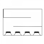
Here is a picture of the design I mentioned above. Pretty self explanatory, with the thick line top left being the vent exit. Cross section is square throughout the pipe, the diagram is birds-eye view.
I thought maybe using a design utilising a square cross section pipe that has been folded and maintains a constant area throughout the bends, with four subs, probably 12" mounted along the front face.
If this idea would work, where does the pipe 'begin', or is the chamber immediately at the rear of the woofers still the pipe? And will having some drivers further away from the pipe cause issues?
Or if there is a better way that I can reach at least 20Hz, with usable output down to 15 Hz being preferable. As for finding a driver with a low enough fs, could I simply take measurements and add mass to the cones? I know that this will reduce sensitivity, but I have enough amplification and car subs are generally high power.
I want to use car subs because drivers of reasonable quality can be had rather cheap and are easy to find.
And to tune the pipe, do I simply make the length 1/4 of the wavelength of the lowest frequency I wish to reproduce? What about width? What speaker parameters do I need to know?
Here is a picture of the design I mentioned above. Pretty self explanatory, with the thick line top left being the vent exit. Cross section is square throughout the pipe, the diagram is birds-eye view.
Attachments
Martin J King has a great site addressing many if not all of these issues
http://www.quarter-wave.com/
😎
http://www.quarter-wave.com/
😎
http://www.avtoybox.com/pdw21250.html
FS - 31.61
RE - 5.59
RES- 59.81
QMS- 4.03
QES- 0.38
QTS- 0.34
L1- 1.88
VAS - 274.29 liters
SPL - 95.4
May be tuned to 20hz or less in a tapped horn.
FS - 31.61
RE - 5.59
RES- 59.81
QMS- 4.03
QES- 0.38
QTS- 0.34
L1- 1.88
VAS - 274.29 liters
SPL - 95.4
May be tuned to 20hz or less in a tapped horn.
Hi-can you just clarify in your post re carpet foam taper...does the taper big end go towards the driver and the narrow end go to the pipe outlet? So...no fiberglass/Dacron is needed for stuffing if you use the taper? I have plenty of fiberglass, or would it be better to use the carpet foam taper?
- Status
- Not open for further replies.
- Home
- Amplifiers
- Pass Labs
- El Pipe-O subwoofers