For distortion vs power could you show Watts on the X axis (assuming you calibrated the voltage and entered the correct load resistance) and % on the Y axis?
Distortion below 10Hz is to be expected due to core saturation. A transformer rated at 30W @ 20 Hz is only rated to 0.3 Watts at 2 Hz.
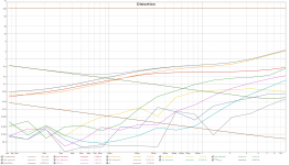
Not sure what's going on with your frequency plot but somethings not right. Attached is one I did for 10 watts output. The traces for higher harmonics finish earlier due to bandwith limitations (sampling rate was 192 kHz). You would expect to see distortion rising at both ends of the curve.
Distortion below 10Hz is to be expected due to core saturation. A transformer rated at 30W @ 20 Hz is only rated to 0.3 Watts at 2 Hz.
Not sure what's going on with your frequency plot but somethings not right. Attached is one I did for 10 watts output. The traces for higher harmonics finish earlier due to bandwith limitations (sampling rate was 192 kHz). You would expect to see distortion rising at both ends of the curve.
Attachments

I've trying to get some change in distortion by varying various components.
LTP CCS current: pot on print to account for jfet variations. Doesn't do a thing.
power tube grid leak: Pot parallel to grid leak. doesn't do a thing (loading down of signal to force some imbalance)
Power tube bias current: Pot parallel to 18R current determining resistor in CCS. Has some effect around 1kHz, huge effect around 50Hz. Unfortunately both have a different optimum.
What more could I try?
The output stage biasing method you have used will result in quite high distortion when measured with sine waves out of the class A region (>~4W). The effective bias current reduces at higher levels because the voltage on the cathodes rises as the capacitor charges up. This has been discussed before on the forum. A potential solution is zener diode clamps to prevent the voltage rising. I think there is also some info on the Tubecad website.
I know you are using that method because you are using toroidal output transformers and want to keep the currents balanced to avoid core saturation, but fixed bias with a servo would result in lower distortion. Or you could try garter bias.
I know you are using that method because you are using toroidal output transformers and want to keep the currents balanced to avoid core saturation, but fixed bias with a servo would result in lower distortion. Or you could try garter bias.
Thanks for the link. I've read it and it is interesting, but 'a bridge too far' for now. I would like to learn some more from my present amplifier. I'm kinda new to every aspect.
@Eli (and others): Are my distortion measurements what you expect? To be honest, I would have expected them to be a bit better. I've read and reread what I could find and the LTP with a CCS should be quite good. The power tubes with CCS should be quite good. I used the Harmonic Equalizer to limit H3 (which does exactly nothing btw...). I have feedback which should kill some more distortion. I have far better output transformers than the 'original' El Cheapo which is said to benefit from better iron.
I also find it weird I have little influence over the distortion. I would at least have thought that I was able to make it worse...

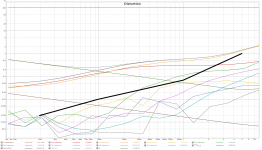
Attached is a simulation showing distortion vs power for your circuit (10k feedback resistor). You can get more power with lower distortion if you went fixed bias.
Increasing feedback reduces sensitivity. You could still get the same power output with more feedback but have to drive it with several volts which your soundcard can't supply.
Increasing feedback reduces sensitivity. You could still get the same power output with more feedback but have to drive it with several volts which your soundcard can't supply.
Attachments
I plotted the THD of your simulation (fat black line) in my measurement ('stock' amp). The THD I achieve is nowhere near the simulation. Is there something fundamentally wrong?
I am surprised that H3 is also dominant in your simulation. I thought tubes were all about low order even harmonic distortion.
I am surprised that H3 is also dominant in your simulation. I thought tubes were all about low order even harmonic distortion.
Attachments
H3 is dominant because it is a push-pull amp. H2 is only dominant in single ended designs. The simulation assumes perfectly matched tubes, so in real life with unmatched tubes you can get a lot higher H2 which can also lead to increased H3. I wouldn't say that there is anything fundamentally wrong.
With conditions from the 6V6 datasheet (fixed bias of -19V, B+ 285V, 35 mA bias current per tube, 8k load) you get 14W at 3.5% distortion from the output stage. With ultralinear fixed bias you might get 2-3% distortion at 11W (I can't find any published figures just now). You only have about 6dB feedback I think, which would halve distortion to 1-1.5%. The front end distortion is minor compared to this. These figures are not all that different to what you are seeing, albeit that at higher output powers your bias method is making things worse.
With conditions from the 6V6 datasheet (fixed bias of -19V, B+ 285V, 35 mA bias current per tube, 8k load) you get 14W at 3.5% distortion from the output stage. With ultralinear fixed bias you might get 2-3% distortion at 11W (I can't find any published figures just now). You only have about 6dB feedback I think, which would halve distortion to 1-1.5%. The front end distortion is minor compared to this. These figures are not all that different to what you are seeing, albeit that at higher output powers your bias method is making things worse.
I've been testing and listening for quite some time now. I've also compared it to my trusty old Philips FA890. W.r.t. hum, the El Cheapo wins (easily). Harmonic distortion is not that different (doing this from memory).
What is different is the harshness w.r.t. to sibilance (hope I have the correct term). The El Cheapo is harsher. Like in 'Over De Muur' by 'Klein Orkest' (Whoops!) at around 0:50.
Is there something I can do about it? Is there a test so I can quantify it? ?
What is different is the harshness w.r.t. to sibilance (hope I have the correct term). The El Cheapo is harsher. Like in 'Over De Muur' by 'Klein Orkest' (Whoops!) at around 0:50.
Is there something I can do about it? Is there a test so I can quantify it? ?
Assuming you don't just have a hf peak. Try 1KHz square wave first to see if there is bad ringing. It not that can be slew rate limiting in the driver stages. Best thing is to try a 10KHz sinewave in and see what comes out.
What are your loudspeakers?
What is their impedance versus frequency?
A high impedance at HF might cause increased amplitude there.
A low impedance at Mid Freq and at HF might cause increased distortion.
Do the speakers have a rising frequency response?
Does the Philips FA890 have a falling frequency response?
Synergy.
You are talking about a complete system, not just an amplifier.
Recorded albums?, Signal source?, Room reflectiveness?, etc.?
Last edited:
I don't have a HF peak. Responses are quite similar for the two amps (suspiciously similar...). See attached graph.
Album (Spotify), signal source (Topping D10s), room, speakers (Jamo S2) and speaker placement is the same for both. But I think I get your reasoning. The output impedance of the tube amp is higher. This means it has trouble sourcing the current for low impedances (resulting in increased distortion) and it is better in sourcing current into a high impedance (too much sound output w.r.t. the average).
The speakers came with the FA890. I got both from my uncle years ago.
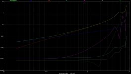
I tried to measure their impedance. It was the first time I ever measured speaker impedance. Beware of beginner errors 🙂 Graph attached. Large peak around 2kHz and slowly rising above. That last part could be fixed with a Zobel network, right?
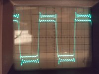
Attached is also a photo of my oscilloscope screen showing a 10kHz square wave as generated by the Topping D10s in 384kHz sampling mode. Unfortunately I do not have a better square wave generator. The input signal (the slightly larger one) shows ringing as the DAC cannot generate a true square wave due to the limited sampling rate. Note the DAC is also ringing efore the 'jump'. I think the output is very similar. The ringing is a bit less due to the limited bandwidth of the amplifier. Otherwise the signal looks fine to my beginner eyes.
Edit: Somehow the scope screen photo is rotated. Time goes from right to left. Don't know what happened.
Album (Spotify), signal source (Topping D10s), room, speakers (Jamo S2) and speaker placement is the same for both. But I think I get your reasoning. The output impedance of the tube amp is higher. This means it has trouble sourcing the current for low impedances (resulting in increased distortion) and it is better in sourcing current into a high impedance (too much sound output w.r.t. the average).
The speakers came with the FA890. I got both from my uncle years ago.
I tried to measure their impedance. It was the first time I ever measured speaker impedance. Beware of beginner errors 🙂 Graph attached. Large peak around 2kHz and slowly rising above. That last part could be fixed with a Zobel network, right?
Attached is also a photo of my oscilloscope screen showing a 10kHz square wave as generated by the Topping D10s in 384kHz sampling mode. Unfortunately I do not have a better square wave generator. The input signal (the slightly larger one) shows ringing as the DAC cannot generate a true square wave due to the limited sampling rate. Note the DAC is also ringing efore the 'jump'. I think the output is very similar. The ringing is a bit less due to the limited bandwidth of the amplifier. Otherwise the signal looks fine to my beginner eyes.
Edit: Somehow the scope screen photo is rotated. Time goes from right to left. Don't know what happened.
Attachments

Last edited:
Yep given 384KHz sampling, the output slew rate is lower than the input so your test is valid. All looks good to me. If thats 10KHz its very good. The output impedance can raise on a valve amp too with frequency. Maybe the resultant response is brighter not sure what to suggest other than a Zobel network. The lower damping factor of valve amps can change the response of the speaker. You can measure the output impedance of the valve amp too.
Last edited:
For the most part, everything looks good.
If I were to try something, I would try a Zobel, RLC that is resonant at 2.3kHz.
The speaker is 30 Ohms at the woofer to tweeter crossover frequency.
If the tube amplifier has poor damping factor, then perhaps . . .
1. The woofer is overdriven at those frequencies, and it breaks up causing harmonics of music at or about 2.3kHz,
2. The tweeter is overdriven at or about 2.3kHz, and generates harmonics.
3. The tube amplifier is unloaded at or about 2.3kHz, and so has large voltage swings at those frequencies, causing harmonic distortion, and/or intermodulation distortion.
4. And, the impedance after the 2.3kHz does not rise until 10kHz, and is not too high at 20kHz either.
5. Right at the resonance of 2.3kHz, the speaker is mostly resistive. But as you go down the impedance slope before, and after the peak, the impedance is inductive, and capacitive, respectively.
That causes an elliptical load on the tube amp, which can cause distortion too.
Just a few thoughts.
Last edited:
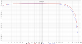
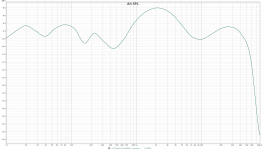
I measured the frequency response into the speakers (as opposed to an 8.2R purely resistive load). See attached graph.
If my math is correct the amps output impedance is 4.9R (based on the 500Hz and 2.3kHz points) giving a damping factor of only ~2. That can't be right, right?
If my math is correct the amps output impedance is 4.9R (based on the 500Hz and 2.3kHz points) giving a damping factor of only ~2. That can't be right, right?
Attachments
I guess it could be. I cannot express an opinion as I don't know. I would pop it in Ltspice to take a look. In terms on reducing it well you already using ultra linear. Many of the diy amps don't have much global negative feedback. That because many like the valve sound but also requires a grasp of feedback theory and stability and understanding the OPT. I think El Cheapo probably does not have much forward gain so it would may be difficult to apply more feedback. I think the poor damping probably accounts to the change in sound you hear.
You may be able to reduce the 10K feedback resistor but this will reduce the gain of your amp and stability. You would need to check with a 1KHz square wave. You may need to add a small cap across what was the 10k and introduce a dominant pole into the design - getting more involved but you have the test equipment and expertise. If you want more forward gain you may need something different to the 12AT7.
- Home
- Amplifiers
- Tubes / Valves
- El Cheapo testing