I have bypassed the NFB resistor increasing the feedback before. Lower THD and lower output volume, but still stable. In the mean time I've found some damping factors in the book 'Modern High End Valve Amplifiers' ranging from 0.7 to 2.4.
If I understand it correctly, the damping factor is highest for triodes, right?
Edit: I see our posts have passed each other in The Channel.
If I understand it correctly, the damping factor is highest for triodes, right?
Edit: I see our posts have passed each other in The Channel.
Triode mode will cut your output power. UL is good. If you want lower damping factor then more GNFB. If you want more forward gain then you could increase the plate resistors less CCS and 12AX7. However the slew rate will get worse. El D did a good job to make this simple to build. I would be trying the changes on simulation first.
Last edited:
As a result of my harmonic equalizer 'research', I got the idea (wrong or right...) that the biggest attribution to the distortion might be the inherent nonlinearity of the output tubes. Then it occurred to me that I might counteract that by (amplitude) distorting the input, which can be easily done on a computer.
First manual optimization attempts show that indeed the distortion can be lowered by a factor of 4 over a wide range of frequencies. Somehow only H2, H3 and H4 are affected.
I have predistorted some music, but haven't been able to tell the difference...
First manual optimization attempts show that indeed the distortion can be lowered by a factor of 4 over a wide range of frequencies. Somehow only H2, H3 and H4 are affected.
I have predistorted some music, but haven't been able to tell the difference...
I might have found something...
For my previous test I used the Behringer UMC204HD as a DAC/ADC. The output level is not that high and also gets distorted the last few dB's so its usable range is even lower. I found that the resistor value of the Harmonic Equalizer did nothing to the harmonic distortion (signature).
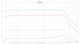
Based on the similar idea as in the post above (distortion created in output tubes) I again focused on the HE resistor, but now with an oscilloscope over it. I found that there was indeed a H2 visible and with increasing input signal of my Topping D10s it became significantly larger. Low and behold: The harmonic distortion of the output depended on the value of the resistor. Turns out 0R is better than 33R! And then I remember this from 'Valve Amplifiers' by Morgan Jones: "Sadly, the author’s experiments indicate that although the equaliser affects all valves, it isn’t always a positive effect."
For the results, see attached graph for the H3 level. The drop at higher frequencies as because the clock of the d10s DAC is different from the Behringer ADC.
The HE resistor is 33R, not the 18R mentioned in the graph.
1) UL 0R
2) UL 33R
3) Triode 0R
4) Triode 33R
And to make matters worse, I had a ~500R resistor in the other channel, which I kinda forgot about as they "didn't matter anyway"...
For my previous test I used the Behringer UMC204HD as a DAC/ADC. The output level is not that high and also gets distorted the last few dB's so its usable range is even lower. I found that the resistor value of the Harmonic Equalizer did nothing to the harmonic distortion (signature).
Based on the similar idea as in the post above (distortion created in output tubes) I again focused on the HE resistor, but now with an oscilloscope over it. I found that there was indeed a H2 visible and with increasing input signal of my Topping D10s it became significantly larger. Low and behold: The harmonic distortion of the output depended on the value of the resistor. Turns out 0R is better than 33R! And then I remember this from 'Valve Amplifiers' by Morgan Jones: "Sadly, the author’s experiments indicate that although the equaliser affects all valves, it isn’t always a positive effect."
For the results, see attached graph for the H3 level. The drop at higher frequencies as because the clock of the d10s DAC is different from the Behringer ADC.
The HE resistor is 33R, not the 18R mentioned in the graph.
1) UL 0R
2) UL 33R
3) Triode 0R
4) Triode 33R
And to make matters worse, I had a ~500R resistor in the other channel, which I kinda forgot about as they "didn't matter anyway"...
Attachments
Last edited:
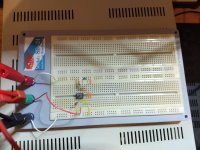
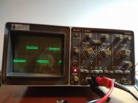
I managed to build my own square wave generator from a 755 that had been lying in a closet for at least a decade.
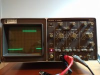
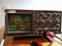
Images are for 1kHz, 10kHz and 10kHz with the feedback resistor bypassed.
Images are for 1kHz, 10kHz and 10kHz with the feedback resistor bypassed.
Attachments
Last edited: