Are you asking about suitable applications and areas of use for the ONSEMI KSP44? Off the top of my head, I can't think of a ready-made audio circuit. In which circuit and where did you test this type?
We shouldn't digress too far in this thread though, I'm primarily concerned here with the Eisenport and comparing the two basic concept ideas (1&2) vs (3&derivatives). But also about how to cleverly limit the quiescent current to a minimum, while still remaining in class A operation and realizing different controller implementations. It is also possible to go into depth. The pros and cons can be discussed controversially. Real setups round off the topic - they show how simple and exciting the subject can be.
Basically, what is missing at this point is a concrete prototype that can be used to carry out extensive listening tests on different loudspeakers.
My quick test has only shown that Eisenport is feasible.
Basically, what is missing at this point is a concrete prototype that can be used to carry out extensive listening tests on different loudspeakers.
My quick test has only shown that Eisenport is feasible.
The free rein...But Citizen124032,
I would be very happy to receive a concrete circuit suggestion...
I've the impression from that post onwards that you're already fixed to this design.
And as I'm not happy nor familiar with these kind of topologies, I'd rather pass.
I do follow the discussion however! Cheerio.
The purpose of R2What function does R2 on the previous schematic perform?
For the time being, and that alone, R2 is a remnant of various thoughts. Its main purpose is to make the current measurable and visible as a voltage drop. Monitoring the quiescent current at two points. In its current form, it remains virtually unused.
@Citizen124032
But that's a shame, because I'm anything but fixated, I'm focused - and it would be interesting to hear more about your discomfort with this topology (known in this and 1001 other threads). Perhaps in a parallel thread?
To my own chagrin, I have to repeatedly state that I have only reinvented the wheel - the iron port idea is also already circulating in this forum in several facets; sorry, if you search hard (and I did justamente, you'll find similar forms aplenty.
This circumstance is somehow demotivating.
HBt.
The esoteric view of R2 as part of an evolutionary remnant
Any alternative practitioner can write a poem about this. I could do the same and write a proper poem. But what's the point? Nothing, except confusion. You /we could imagine so much, but a few measurements (primarily the time signal and spectral analysis, of course) under complex load would be useful.
I would compare, with and without spleen (R2), also between "C1 connected to the source of Q1" and / or to "the drain of Q2". A different starting point of the bootstrap could make a decisive difference in terms of SRPP. Could!
You /we could also philosophize about the internal resistance ... or implement an electronic fuse like #76.
Thank you Nelson for your question. Standing freely in space, this resistance seems really strange - but it is basically just a remnant of the discovery process.
Whether it can do any good, I don't know - often a gut feeling, an intuition simply tips the scales.
Whether it can do any good, I don't know - often a gut feeling, an intuition simply tips the scales.
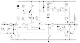
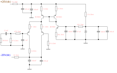
With the greatest of respect, something irritates me about the question of the meaning of R2 - and that is why I am attaching the schematic showing the possible options.
Consequently, R19 must also be questioned - which is also a remnant of the process of discovery, of evolution. Which is far from complete.
All the practical, metrological tests recommended above #87 should also be carried out with R19 against
a) GND
b) -Vcc
c) +Vcc.
Additionally!
All in all, this is already a fairly extensive measurement or rather investigation task, each in two different domains. At the same time, you /we, (I) also always observe the static behavior, or rather check it.
Attachments


As an additional, local negative feedback, we could also transplant R2 into the source branch of Q2 ... this is often done.
A seemingly harmless question catapults us directly into the depths of circuit design.
Another good question would be about the benefits of C1. Cumbb prefers to omit this very important detail, why?
But a lot of things are already sorted out in the simulation phases or double-checked.
And now the monologue ends - The epilogue to season one.
C1 ref diagram 1? Perhaps I'm wrong as a wholly self educated "EE" but it looks to create an AC bootstrapped current source in series with a current source that works to DC, so the load of Q4 would decrease by removing it, thus reducing its gain. Whether and at what frequencies the effect is consequential at all, I don't know (Ro Q4, Cin Q1 being parallel).

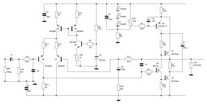
Reffering to the circuit in #73, shooting session:
The current source around Q5 is injecting supply noise into the circuit - there are way better solutions, decades since.
The singular output of the input diff causes other challenges for the circuit - go balanced or not, not halfway everything to please.
C5???
VR2 - nasty thing.
R12/R13 51E - why, what current, what consequence to the open loop gain, a very delicate spot in the design, much overlooked.
Depending on the supply rail, R8 may cook. Why R9.
R10/R11: 1k0 - why? Calculations for stability, noise, issues...
R7, a stopper, value confirmed with specs of the 510?
Cx???
Q1/Q2 are in quasi-complement arrangement, a fundamental choice - why why why???
R1/R2 already issued by NP.
C1 a somesort of SRPP solution>?
Another one: VR1, also nasty.
Pots should not appear in good designs. They show the imperfections of the design.
C2 "1mF" - ehmm...
R19 'MOX'?
C6 uni or bipolar? What is the residual dc voltage on the bases of Q6/Q7, and during powering up/down?
Q3 as current source 'in promotion' of the load current by Q1, but not by Q2 by choosen design - ouch.
Open loop bode plots show...?
Thermal issues addressed?
Startup/shutdown sequence simulations performed?
This is not my kind of amplifying, but do respect other approaches no matter what: engage!
Cheerio~
Engage
UBtr - 5.6V = 14.4V
Pv = (14.4V)^2 / R8 = 138mW
R8 will therefore not "boil" under any circumstances.
I have the suspicion that the criticism is directed at the method, the procedure and not the functional circuit itself.
#
I have the suspicion that the criticism is directed at the method, the procedure and not the functional circuit itself.
I can deal with that very well and I look forward to a concrete counter-proposal, as well as a discussion of methods and didactics.
Should I open a new thread for this (case)?
kindly,
HBt.
As an example, I'll pick out your short comment on the R8 from the series of question marks.(...)
UBtr - 5.6V = 14.4V
Pv = (14.4V)^2 / R8 = 138mW
R8 will therefore not "boil" under any circumstances.
This automatically raises the question of the preferred type of amplification for your flavor.This is not my kind of amplifying, but do respect other approaches no matter what: engage!
Cheerio~
I have the suspicion that the criticism is directed at the method, the procedure and not the functional circuit itself.
#
I have the suspicion that the criticism is directed at the method, the procedure and not the functional circuit itself.
I can deal with that very well and I look forward to a concrete counter-proposal, as well as a discussion of methods and didactics.
Should I open a new thread for this (case)?
kindly,
HBt.
Notes
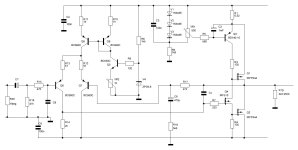
This two-stage concept is (also) known as low feedback. For the first stage in the case of the open loop, this means that the linear factor is only slightly greater than 10; with the band limit now revealed, the cut-off frequencies are far outside the audible frequency spectrum. The criticized PSRR of the current mirror is decisively improved from |50dB| to over |100dB| by inserting the obligatory support and block capacitors, see appendix.
This two-stage concept is (also) known as low feedback. For the first stage in the case of the open loop, this means that the linear factor is only slightly greater than 10; with the band limit now revealed, the cut-off frequencies are far outside the audible frequency spectrum. The criticized PSRR of the current mirror is decisively improved from |50dB| to over |100dB| by inserting the obligatory support and block capacitors, see appendix.
Attachments
Granted, but it's not the method itself (it might lead to a good design, yet not my flavour), nor the procedure to yield a functional amplifier.I have the suspicion that the criticism is directed at the method, the procedure and not the functional circuit itself.
I can deal with that very well and I look forward to a concrete counter-proposal, as well as a discussion of methods and didactics.
It is however, the very design itself.
What I see are chunks and bits of other designs, put together in a 'modern' fashion.
A thermal stable current source (a j-fet & bjt compound, 80's) outsmarts these commonly used two bjt judo gripping sources by far (not in this cicuit!). I'd rather prefer a very modern chipped cs instead, as these proove te be of extreme good and stable quality. The cs in this circuit (Q5) is really outdated, unreliable, noisy and troublesome (#93).
Do not put a differential stage balancing on one output leg only. It's virtue is the balance, not de-balancing once the signal has left the stage. It's a one hand piano player.
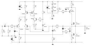
The core of the amp is Q4, The IRF510.
I'm not used to work (think/design/&c) with mosfet's, as I'm from the preceding age. When I was a student, mos was inverented recently so I did not master the fine essentials of them. But they are fine, great, but beyond my scope. I leave that to others gracefully.
But is is the core of the amp, no matter what semiconductor is used. The amp should be fashioned around it to lift it to it's peak performance.
How is it fashioned? Cx and a BD140-10 (not a 16?) in a q-comp setup. No tweaking, no finesses, no deep thoughts. C1 as a bootstrap harnessing that BD140 cs, as if it is a resistor arrangement from the 70's. Are these the fruits of the current insights?
Instead of throwing things over the hedge (I'm not native english, but I'm sure you'll understand), I've been busy for several years now to develop an Hiraga 'on steroids', balanced and bridged, solid twice output based upon the 8W version, delivering 30+W running at 4 x 1.5Adc in the totem poles. Run through a zillion simulations now, no pole compensation needed, by surprise (huh???), phase flat from dc to >100k. The Hiraga design outperforms anything actually.a concrete counter-proposal
I dare no to post this as it is not prooven in my opinion, and never build. Only a setup is made, and all layout consideritions went overboard in the process. The diff pair is on handwidth distance, drivers and finals are 'tombola selected' counterparts 1943/5200. Everything is running warm, near hot.
Once settled (starting up / shutting down,), a modulation (the signal to be amplfied) seems insignificant...
I would use identical trannies to Q1 and Q2 as Q4 in order to achieve maximum homogeneity.
The Hiraga Le Monstre, and Classe A, is indeed - for complementary transistors PP - an extremely good amplifier - also because it is half-wave symmetric. But because it amplifies the half-waves separately, and thus audibly amplifies them differently, and also runs on half-wave separated power supplies, it is not a hi-fi or high-end amplifier. But it is a great party machine that you can also use to listen to music at home.
In my opinion, balancing and other PiPaPo is an improvement for the worse, which will definitely not lead to more musical enjoyment and pleasure. I would look for appropriate speakers and enjoy the small tuning work regarding materials, components, placement and so on;-)
One piece of advice: don't use (e.g. 1943/5200) TO-3Ps.
Although they sound very silky and fine for their size, they are also overhanging and don't get the notes together, dragging out the tempo...-(
Last edited:
Now I am convinced that we need an offshoot thread.
There the preferences and fundamental rejections of other basic circuits (or components and dimensioning issues) can be better discussed - the stew cooked.
Glaubensfragen
There the preferences and fundamental rejections of other basic circuits (or components and dimensioning issues) can be better discussed - the stew cooked.
Glaubensfragen
Dear Citizen,
I fully understand your objections, but in my opinion they are slightly exaggerated - because the intention of this thread is not a fashionable design for the next millennium. Please let us now discuss such points and aspects in the new thread created for this purpose, with specific circuit examples if you like.
So my appeal is, let's (also cumbb) use the other pot for this.
Whether Eisenport 1 is good or bad will be decided by the final measurements on the finished object itself and the user with his loudspeaker cabinet (in the room).
With this in mind,
HBt.
- Home
- Amplifiers
- Solid State
- Eisenport - Three ideas in class A operation