I can only fully agree with that.
Important note
The three ideas of "the Iron Port" are merely ideas in every respect. 1 & 2 are not fully developed at the present time, I would not give a functional guarantee (suitability for everyday use). To be honest, there are still a lot of design issues - and the hours spent on the simulator just fly by. You could follow the structure and method of the Siemens BUZ-Amp or Marcel van de Gevel's example ("Audio power with a new loop" EW02-96), but that would basically be like writing it off.
If we stay (briefly) with possible A operation in push-pull mode and assume a static load of 8 ohms, then (in my opinion) a quiescent current of 1.25Adc should flow permanently through the output stage. The famous >0.8A comes from the 1.25 / sqrt(2) idea, but is that really true? That would be nice.
But now we would already need two pairs of IRFs.
Considering that the fets are actually there to switch loads, for example PWM or motion controllers, unwanted behavior is always to be expected. And the same applies to the first two ideas, the JLH-like output stage.
But now we would already need two pairs of IRFs.
Considering that the fets are actually there to switch loads, for example PWM or motion controllers, unwanted behavior is always to be expected. And the same applies to the first two ideas, the JLH-like output stage.
Power and class issues
Basically, U*I=P
and for direct currents the topic is really easy to understand. If we remember that we are talking about an area (the product), it becomes even easier.
A practical example; Elektor magazine (issue 10/91) advertised the "Class A LFA" as a 50 watt amplifier with an optimized Class A setting. Further on in the advertising text we read, "and remains in class A up to the -3dB level limit /clipping /max swing".
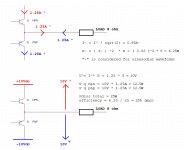
The output stage is a compound arrangement with the famous Sanken ring emitters BJTs. The quiescent current is a total of 1.255Adc, the power supply is regulated at +/-30Vdc. This means that the output stage can be savely driven at least up to 27Vpeak without clipping if the power supply can also supply the necessary load current. The load is specified as a static 8 Ohm and everything is considered in steady state.
Peak power (under sinusoidal control),
(27V)^2 / 8Ohm = 91.125Wp Now the power supply unit should be able to deliver at least 3.375Ap. However, the power comparison is based on the identical heat that a direct current would cause, so we should (or even must, or we must integrate) use the effective values of the voltage and current - RMS - for the calculation. Everything else is just eyewash.
(19.092Vrms)^2 / 8Ohm = 45.563W, the addition RMS is usually omitted.
10 *log(45.563W/91.125Wp) = -3dB
However, the quiescent current is only 1.255Adc.
Break
(1.255A)^2 * 8Ohm corresponds to 12.6W or 10.04V * 1.255A according to the known formula or the calculation of a square area.
However, Elektor speaks of 50W in an optimized class A setting (see the power rating of -3dB), how can this be explained?
Quite simply, one considers the case dynamically, i.e. in ac-view, and imagines two identical sources in parallel -> in push-pull, not single-ended mode.
Now we can calculate with (2*1.255A)^2. This results in the 25Wrms for a static load of 8Ohms in a stationary state (that we have already assumed in the back of our minds). The peak power under the sinusoidal consideration is simply twice as much, i.e. 50Wpeak.
Single-ended = 12.5W vs. push-pull = 25W.
Conclusion
In reality, the Elektor amplifier is a 25W type.
Basically, U*I=P
and for direct currents the topic is really easy to understand. If we remember that we are talking about an area (the product), it becomes even easier.
A practical example; Elektor magazine (issue 10/91) advertised the "Class A LFA" as a 50 watt amplifier with an optimized Class A setting. Further on in the advertising text we read, "and remains in class A up to the -3dB level limit /clipping /max swing".
The output stage is a compound arrangement with the famous Sanken ring emitters BJTs. The quiescent current is a total of 1.255Adc, the power supply is regulated at +/-30Vdc. This means that the output stage can be savely driven at least up to 27Vpeak without clipping if the power supply can also supply the necessary load current. The load is specified as a static 8 Ohm and everything is considered in steady state.
Peak power (under sinusoidal control),
(27V)^2 / 8Ohm = 91.125Wp Now the power supply unit should be able to deliver at least 3.375Ap. However, the power comparison is based on the identical heat that a direct current would cause, so we should (or even must, or we must integrate) use the effective values of the voltage and current - RMS - for the calculation. Everything else is just eyewash.
(19.092Vrms)^2 / 8Ohm = 45.563W, the addition RMS is usually omitted.
10 *log(45.563W/91.125Wp) = -3dB
However, the quiescent current is only 1.255Adc.
Break
(1.255A)^2 * 8Ohm corresponds to 12.6W or 10.04V * 1.255A according to the known formula or the calculation of a square area.
However, Elektor speaks of 50W in an optimized class A setting (see the power rating of -3dB), how can this be explained?
Quite simply, one considers the case dynamically, i.e. in ac-view, and imagines two identical sources in parallel -> in push-pull, not single-ended mode.
Now we can calculate with (2*1.255A)^2. This results in the 25Wrms for a static load of 8Ohms in a stationary state (that we have already assumed in the back of our minds). The peak power under the sinusoidal consideration is simply twice as much, i.e. 50Wpeak.
Single-ended = 12.5W vs. push-pull = 25W.
Conclusion
In reality, the Elektor amplifier is a 25W type.
Let's take the MF-A1 as another example, with the typical 0.8A quiescent current and calculate (2*0.8A)^2 * 8Ohm = 20.48Wpeak.
If the 0.8A represents the absolute peak, the maximum level of the current curve over time, then we can now speak of 20.48Wp -> for push-pull A operation this is logically 10.24Wrms.
But sqrt(8Ohm * 20.48Wp) = 12.8Vp, i.e. conversely, a little more would be possible in terms of voltage. And the A1 is known to be controllable up to the rails (at this moment it goes up in smoke, but that's another topic). (20Vdc)^2 / 8Ohm = 50Wpeak ---> 25Wrms.
However, these maximum 25 watts are no longer A-class watts.
Correct
for 20W the power amplifier must be driven up to 18V - peak. This corresponds to a current of 2.25A - peak. As a comparable RMS value, this is exactly 1.591A. Tim de Paravincini has halved this value due to the dynamic approach of push-pull operation and therefore arrives at 0.8A quiescent current.
If only that were true, it would be so nice - but unfortunately it is not.
2 times the quiescent current corresponds to the maximum peak current in push-pull operation shortly before the end (smoke) and the begin of true Class-B. In between lies the AB operation.
In single-ended operation, in the present case of the Eisenport project, one can only speak of 5.12W. In push-pull of 10.24W.
Everything above this is already subject to the rules of AB operation (Douglas Self diction).
Everything above this is already subject to the rules of AB operation (Douglas Self diction).
Aside: Complementary-transistors-push-pull has nothing to do with "high end" - Classe A or not.
I would prefer a SE;-)
I would prefer a SE;-)
That is also my opinion. I think we should also look at this project thread in a completely value-free way, i.e. totally open in every direction.
😉
There is a lot of controversy about JLH69 and you /we don't really know what it is. But with the PASS ZEN you /we know it exactly. With the MF-A1, you'd /we'd probably like to know.I would prefer a SE ;-)
😉

![DSCN0214[1].JPG](/community/data/attachments/1205/1205504-4137aa1d7e09bb073641f8c363ed8096.jpg?hash=QTeqHX4Juw)
100 % consensus
(I want to submit the latest iteration of the first idea right away, simulated, i.e. in the computer, it is already detailed ... which definitely leads to extreme sleep deprivation. I'll draw up the circuit diagram in a moment and then I'll start a test setup in the next few weeks. The exciting result for me, however, is the fact that the distortion spectrum almost corresponds to the current A1 publications, at least in the computer, if I remember correctly).
(I want to submit the latest iteration of the first idea right away, simulated, i.e. in the computer, it is already detailed ... which definitely leads to extreme sleep deprivation. I'll draw up the circuit diagram in a moment and then I'll start a test setup in the next few weeks. The exciting result for me, however, is the fact that the distortion spectrum almost corresponds to the current A1 publications, at least in the computer, if I remember correctly).
Second stage
A classic negative feedback, three resistors and a coupling capacitor and the inverting amplifier would be ready. It already simulates itself really well and is almost rail-to-rail controllable, and as an inverted version it is also completely uncritical and stable. The bandwidth is greater than 300kHz. Even if I have absolutely not copied (from Nelson Pass), the whole scenario is ultimately no coincidence. The tools are the same, the rules are the same ... R_load equal 8Ohms.
Ok 🙂, i'll try it.

First stage plus ...
If I remember everything correctly (the file is at home on an old computer), this is the result of my nightly simulations. Of course it's not complete, but it gives an impression. Some tricks and physical couplings are still necessary to compensate for the thermal drift. But I am very confident and completely satisfied with the predictions. The construction will ultimately show.
Kind regards,
HBt.
The JLH, i.e. the three trannies, is incredibly stable. I've built dozens, and none of them ever needed emitter/source resistors. I also see this as an advantage, because good-sounding resistors are rare. The wirewound, ceramic ones sound gray, grainy, coarse. As power resistors, film resistors in TO- housings are the best choice.
Getting the feedback via a differential amplifier adds a transistor unnecessarily. Compared to feedback via the input, the sound is doughier and less clear.
Getting the feedback via a differential amplifier adds a transistor unnecessarily. Compared to feedback via the input, the sound is doughier and less clear.
Very interesting points
Can this phenomenon, i.e. the cause, be described technically correctly?
The project seems to be very exciting and positive, I'm really looking forward to it - and to simply trying out all sorts of things.
Can this phenomenon, i.e. the cause, be described technically correctly?
The project seems to be very exciting and positive, I'm really looking forward to it - and to simply trying out all sorts of things.
What?? Noone can hear a metal resistor! Unless of course its inductance is making the circuit oscillate, or its Johnson noise is high enough.I also see this as an advantage, because good-sounding resistors are rare. The wirewound, ceramic ones sound gray, grainy, coarse.
Metal film or MOX should fit well. But why not be specific - and make an exact component recommendation? A source of supply would also be great. I would be happy to try it out.
My question about a technical or mathematical explanation is aimed at the point with the NFB - and I don't want to anticipate anything, but rather be completely open to the knowledge and opinions of others. Otherwise the exchange of ideas is unnecessary and not refreshing.
I'm looking forward to the JLH, PLH, xyzLH ... like design, and positive, constructive drive would just be nice - in every direction.
The ear perceives differences, which it reconstructs into frequencies, into music. What is modulated by material on a micro level is audibly represented on a cubic meter scale: components modulate the signal audibly considerably,
A comparable example are musical instruments: such as the body and strings, or teeth and skull. Teeth vibrate, resonate, (frequencies) which has a considerable effect on the entire organism via the electrical network (nervous system). If you have teeth extracted, you may have to have the opposite half of the body (two halves of the body, equal to stereo, or even two-half-waves-amplification) extracted as well, otherwise the entire organism will be thrown into chaos, even to the point of collapse. In the case of teeth - or two-half-wave amplifiers, symmetry is the key;-)
A comparable example are musical instruments: such as the body and strings, or teeth and skull. Teeth vibrate, resonate, (frequencies) which has a considerable effect on the entire organism via the electrical network (nervous system). If you have teeth extracted, you may have to have the opposite half of the body (two halves of the body, equal to stereo, or even two-half-waves-amplification) extracted as well, otherwise the entire organism will be thrown into chaos, even to the point of collapse. In the case of teeth - or two-half-wave amplifiers, symmetry is the key;-)
A beginner's exercise for you, Mark: place your amplifier on different materials (wood, metal, stone, glass, rubber...) and listen;-)Noone can hear a metal resistor!
Last edited:
I know exactly what Cumbb was saying - and I even agree; there is a completely plausible physical, technical and mathematical explanation for this. But I don't want to (have to) take the lead, I'd rather just go with the flow and meet friends.
In the end there will be a functioning amplifier on the table, there's no question about that - without wound wire resistors.
In the end there will be a functioning amplifier on the table, there's no question about that - without wound wire resistors.
- Home
- Amplifiers
- Solid State
- Eisenport - Three ideas in class A operation