be Positive
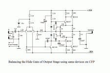
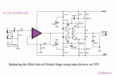
the magic equation is dedicated to the CFP final power (different hFE)
to the voltage stage
the remedy to crossover distortion is increase the current driver (EF stage)
😱
really don't think this probe amplifier have😉
the magic equation is dedicated to the CFP final power (different hFE)
to the voltage stage
the remedy to crossover distortion is increase the current driver (EF stage)
😱
really don't think this probe amplifier have😉
Stee,
both master and slave must be biased in class A to avoid saturation charge-storage problems.
both master and slave must be biased in class A to avoid saturation charge-storage problems.
Re: of course
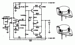
Wow, where's this from. Looks like a flaming tiger. Vintage 2N3055's had only 800kHz Ft.
Stee said:class A is the best that you can have
but what do you think about this news
(same driver as final on CFP)?
Wow, where's this from. Looks like a flaming tiger. Vintage 2N3055's had only 800kHz Ft.
Re: Re: of course
And 741 with 1MHz ULG and 0.5V/uS slew rate.
scott wurcer said:
Wow, where's this from. Looks like a flaming tiger. Vintage 2N3055's had only 800kHz Ft.
And 741 with 1MHz ULG and 0.5V/uS slew rate.
OMG
High power output transistors as drivers?!
Another silly idea from you, Stee!
Enough for me!
I never gonna read your posts anymore!!!
High power output transistors as drivers?!
Another silly idea from you, Stee!
Enough for me!
I never gonna read your posts anymore!!!
Opamp at input with +-35V supply?? Wake up, Stee....
And "current limiter" with showed values is nonsens. Try some simulator before posting those "schematics".
And "current limiter" with showed values is nonsens. Try some simulator before posting those "schematics".

BV said:Opamp at input with +-35V supply?? Wake up, Stee....
And "current limiter" with showed values is nonsens. Try some simulator before posting those "schematics".
Output devices are rated up to 16A. Current limiter will protect them until fuses blow. However, 1 Ohm resistors need to be rated correspondingly (I had bad experience with wirewound resistors that burst in flame recently).
1ohm, 16A , Pd 256W, output devices about the same...and 16V from Ub lost.
PMA- Yes, it can be also discrete OA. You like those Stee´s inventions?
PMA- Yes, it can be also discrete OA. You like those Stee´s inventions?
It seems as if you could omit the BC546B/BC556B with their diodes and resistors in the center of your schematics in posts #47 and #50. The two diodes that are in parallel to them will always pull the bias to ~1,3 V, whatever those transistors try to achieve.
How do you compensate for the ~500 mV DC offset at the output? You should really not recommend building this thing, before it is safe to use. There are many beginners in the forum, who cannot judge the possible consequences.
How do you compensate for the ~500 mV DC offset at the output? You should really not recommend building this thing, before it is safe to use. There are many beginners in the forum, who cannot judge the possible consequences.
I´d suggest mods delete all schematics and lock this thread before anyone blow up their gear, trying to replicate stee´s stupid ideas.
Tekko said:I´d suggest mods delete all schematics and lock this thread before anyone blow up their gear, trying to replicate stee´s stupid ideas.
Post #43 looks like it's been burning fingers for a long time.
🙂
you are nice friend
to answer my stupid inventions
audio-gd make op-amp for dual 35V PSU
But nobody has yet expressed an opinion
on the key point of the project
the issue of hide-gain income
(the simulator does not allow for)
what you think about the CFP high power driver?
Regards😀
to answer my stupid inventions
audio-gd make op-amp for dual 35V PSU
But nobody has yet expressed an opinion
on the key point of the project
the issue of hide-gain income
(the simulator does not allow for)
what you think about the CFP high power driver?
Regards😀
>> the issue of hide-gain income
>> (the simulator does not allow for)
How do you know when you obviously never cared to use one?
>> (the simulator does not allow for)
How do you know when you obviously never cared to use one?
According to your drawing from post #27 hFE(1)/hFE(2) = hFE(3)/hFE(4).
Put some numbers to it. Is hFE(1)@45mA(Ic1)/hFE(2)@90mA(Ic2) = hFE(3)@4050mA(Ic3)/hFE(4)@4050mA(Ic4)?
Put some numbers to it. Is hFE(1)@45mA(Ic1)/hFE(2)@90mA(Ic2) = hFE(3)@4050mA(Ic3)/hFE(4)@4050mA(Ic4)?
- Status
- Not open for further replies.
- Home
- Amplifiers
- Solid State
- eine fantastische Verstärker/Endstufe


