Source follower. You need current, it's got current. You need low source Z, it's got low source Z, and small enough to make using individual followers for each output tube be practical. That allows direct coupling to each tube's grid.
Have a look at mosfetfollie the second picture shows how to apply a source follower when using an amplifier with fixed bias. I am to noob for this, but I think you may easily run the mosfets hot enough for class 2 operation of the 807's.
Morgan Jones CP is on my priority list, but it's biasing circuit does not allow one to connect paralleled output tubes and bias them individually.
Hope this help, Erik
Much has been written about the "sound" of TRIODE cathode followers and mitigating persceived problems it by current source loading them to put them in near constant current mode and bootstrapping them to put them in near constant voltage mode.
I found the same thing. Now, if you keep that constant voltage low enough you can run big current without over dissipating the tube. Now triode wire a few big sweep tubes, and you will see where I am going with my output stage. Need a big bunch of drive voltage though.
To drive 8 X 807 (or any tubes), consider a PowerDrive circuit with a seperate mosfet for each tube.
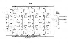
807 x Eight Output
I have revised a little bit more..I like it very much this way.
I think it will work fine and I sense you folks may think it is worth a twirl around the block. The big question; what will drive it?
The 100R's could be exchanged for 150R's or even better an inductor type.
The 47nF has been corrected to .47uF
The 680R is swapped with a 10R
50K bias R's and pot are still 50K's
Attachments
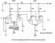
807 Pre by Darrell Whitfield
Folks,
I pulled this up on Photoshop and tried to draw it again so perhaps this time a better look see. I posted it already but it went by without notice or criticism. I would LOVE to hear your thoughts 'cause I though it was ingenious if not wacky?
Check this circuit out and tell me what you think. And don't forget to look at the tube data sheets before...!
Cheers,
Shawn.😉
Attachments
still think you need a follower (either tube or mosfet) though.
Thinking out loud, what about 2 Aikidos (in a PP configuration), with input transformer phase split.
Thinking out loud, what about 2 Aikidos (in a PP configuration), with input transformer phase split.
agent.5 said:still think you need a follower (either tube or mosfet) though.
Your thoughts just like everyone else's are very important to me but I would like more detail. Show me the achilles heel that you see.
Cheers,
Shawn.
TomWaits said:
Your thoughts just like everyone else's are very important to me but I would like more detail. Show me the achilles heel that you see.
Cheers,
Shawn.
a little dual triode does not have enough current to drive the capacitance of the grids of 8 output tubes.
agent.5 said:Thinking out loud, what about 2 Aikidos (in a PP configuration),
WOW! I was looking at the Aikido for hours last night but I don't know what to make of it in this application.
Cheers,
Shawn.
agent.5 said:a little dual triode does not have enough current to drive the capacitance of the grids of 8 output tubes.
The tubes can change. The support components can change. I like the simplicity of the "Whitfield" circuit the most. It may cause me some power supply grief but I would rather complicate the power supply a little vs. adding more stages that "may" not be required in the amplifier.
Thank you for taking the time to comment. I hope I'm not being too stubborn to you all. Most of you have light years of experience ahead of me. I feel honored to have this exchange with you all.
Cheers,
Shawn.
The Whitfield circuit has a cathode follower. I think it is in disguise...please study the schematic. Perhaps I am wrong?
Shawn.
Shawn.
TomWaits said:
WOW! I was looking at the Aikido for hours last night but I don't know what to make of it in this application.
Cheers,
Shawn.
aikido has 2 stages. The first stage has the top triode loading the bottom triode; the second stage is a cathode follower. So there is your follower. Now a single Aikido is single ended; for push pull, you need 2 of them.
TomWaits said:The Whitfield circuit has a cathode follower. I think it is in disguise...please study the schematic. Perhaps I am wrong?
Shawn.
not on the schematic posted on post#44, as the signal outs are taken from the plates. A cathode follower means that the signal outs are taken from the cathode.
On your earlier schematic, the diff amp performance is degraded by paralleling already-mediocre current sources. Use a single discrete CCS in that critical spot. And then you can lose the balance pot. Also, you'll probably need to connect a leak resistance between the two grids of the second diff amp.
SY said:On your earlier schematic, the diff amp performance is degraded by paralleling already-mediocre current sources. Use a single discrete CCS in that critical spot. And then you can lose the balance pot. Also, you'll probably need to connect a leak resistance between the two grids of the second diff amp.
Yes the current source on the 6DJ8 needs a true discrete CSS and the second stage with the 5687 remains a little wonky. Still I thought it was clever ramping the current up and using a greater power supply difference on the second stage to achieve a higher voltage swing.
I'll try to tweak it.
Shawn.
Hi SY
I still would keep the pot, because the 2nd stage is DC-coupled. The CCS only guarantees AC symmetry, but not DC symmetry.
Also, in such a setup - LTP followed by diff amp - really perfect AC symmetry by a true CCS is not strictly needed, since the diff amp will deal with slight non-symmetries easily, after all that is one reason diff amps are for.
For such setups, I feel that stabilized feed voltages for the 1st stage are much more important than a super-duper CCS.
Regards,
Tom
(frontend extract of one of my amps attached)
SY said:On your earlier schematic, the diff amp performance is degraded by paralleling already-mediocre current sources. Use a single discrete CCS in that critical spot. And then you can lose the balance pot. Also, you'll probably need to connect a leak resistance between the two grids of the second diff amp.
I still would keep the pot, because the 2nd stage is DC-coupled. The CCS only guarantees AC symmetry, but not DC symmetry.
Also, in such a setup - LTP followed by diff amp - really perfect AC symmetry by a true CCS is not strictly needed, since the diff amp will deal with slight non-symmetries easily, after all that is one reason diff amps are for.
For such setups, I feel that stabilized feed voltages for the 1st stage are much more important than a super-duper CCS.
Regards,
Tom
(frontend extract of one of my amps attached)
Attachments
I just got home from work and found two large boxes on my front porch. I opened one box and found the biggest freakin toroid that I ever held. I saw the picture in one of the earlier posts, but that didn't sink in. These things are large by big by immense by heavy! They are bigger than a 1.5 KW isolation transformer. This brings up my first concern. If they were indeed designed for a bass guitar amp, there may be a problem with the high frequency response. My first experiment will be to test this, unless someone out there already has.
OK, first panic attack, over. My last monster transformer sucked above 10KHz. I rigged up a quick frequency response with a signal generator and scope and another test with an HP8903 audio analyzer.
At 20 KHz this transformer is down 0.17db compared to 1Khz. At 20 Hz the transformer is 0.06 db down. At 5Hz it is down 1.1 db (lower measurement limit) and the upper 3 db point is 71KHz.
The transformer is marked 400 watts at 20 Hz. This thing could easilly handle a kilowatt at guitar frequencies. I just gotta hook this thing up, like tomorrow! Maybe the thread starter needs some more 807's!
At 20 KHz this transformer is down 0.17db compared to 1Khz. At 20 Hz the transformer is 0.06 db down. At 5Hz it is down 1.1 db (lower measurement limit) and the upper 3 db point is 71KHz.
The transformer is marked 400 watts at 20 Hz.
Not bad for around $130 each.
tubelab.com said:At 20 KHz this transformer is down 0.17db compared to 1Khz. ...the upper 3 db point is 71KHz.
Scandalous by Plitron standards. What was the source impedance?
I used a 600 ohm signal generator (HP204C) with a 620 ohm resistor in series. Close enough for a 1250 ohm transformer. It was loaded with an 8 ohm resistor on the 8 ohm tap.
Things may change with 6 or 8 tubes (or 4 big tubes) and several hundred milliamps of current hooked up to it. It still looks far better than the 280 watt Hammond or the surplus Fender transformers found on Ebay, and it is cheaper. I will hook some type of P-P tube circuit up to this guy this weekend. I haven't decided what yet, depends on what parts that I can find here.
Things may change with 6 or 8 tubes (or 4 big tubes) and several hundred milliamps of current hooked up to it. It still looks far better than the 280 watt Hammond or the surplus Fender transformers found on Ebay, and it is cheaper. I will hook some type of P-P tube circuit up to this guy this weekend. I haven't decided what yet, depends on what parts that I can find here.
- Status
- Not open for further replies.
- Home
- Amplifiers
- Tubes / Valves
- Eight 807's in Push Pull?