Dude,
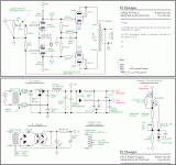
You can "lift" the cascoded MOSFET CCS from the "El Cheapo" schematic I've uploaded. McShane has all the parts needed for that "beast".
As SY stated, even the simplest CCS works well in the tail of a LTP. So, the popular IXYS 10M45S is a decent choice.
You can do much better than shown in the HF89 schematic, for a bias supply. Full wave bridge rectify the power trafo's discrete bias winding using 4X Schottky diodes and follow with a CRC filter. The 1 A./130 PIV rated Fairchild FMKA130 is well suited to the job. 100 WVDC caps. are fine in the bias supply filter. Caps. have a surge margin, while "sand" diodes fail if subjected to excessive voltage.
At a minimum, use a separate bias trim pot. in each channel. FWIW, I'd use combination bias, with a shared 100 Ω/470 μF. network under each PP pair's cathodes. Combination bias makes a single trim pot. in each channel work well and it also "eats" some of the potentially excessive Volts in the B+ rail. Please notice that using a 100 Ω cathode bias resistor makes setting the "idle" current very easy.
Attachments
Bingo... when I can SEE it, I can start to understand it. Thank you Eli, I will study this schematic.
Hold your banjo, sports fan!
Your original post was that the amp was thin, flabby and not detailed. Keep that in mind.
All your caps are squirrel turds. Replace them. Every last one, and one at a time. Snip, solder, snip, solder. Then, make sure it still works. Then listen to the amp. See how it sounds, which is likely to be different - thin, flabby, not detailed screams caps to me in an amp that old. Then, you can decide what you want to change next sound wise, and post here again. The excellent tech advice you are getting here is not going away any time soon.
If you have more hours with a real gun than a solder gun, the last thing you want to do is gut the poor thing only to find that it does not work at all and various parts go poof. In theory, this is all integer math and following pictures. In practice, it is sourcing the right parts, attention to detail and not biting off more than you can chew at once.
Have fun, and let us know how it goes!
Replacing all caps is a given, and with Jim McShane's help. The replacement parts have been determined.
My soldering/assembly skills are solid. No worries. After more careful inspection I don't like a lot of what I am seeing inside this amp. I'd prefer to do it right, not do it twice. I will be gutting it and keeping only the usable hardware, trafos resistors and tubes.
Here's the task list:
-Re-cap
-CR1,2 1000 PIV 3 amp UF5408 Vishay fast diodes to handle increased current, faster and quieter
-Eliminate piggyback heater supply connection for 12ax7. Replace with new regulated PS
-Replace R27 and 28 cathode resistors with 250 ohm for modern line voltage to reduce idle current. R27 to ground instead of to 12ax7 heater.
-Tap into unused Trafo leads and add HF-89 fixed bias circuit.
-3 wire AC supply and ground chassis
-Bypass input trim pots and stereo/mono switch.
CCS is still on the table.
You only do one of the above if you choose to use stock HF-87 or stock HF-89 style bias unless you plan to follow Eli's advice to do combination bias. In that case, the cathode resistor is 100R per Eli suggested.-Replace R27 and 28 cathode resistors with 250 ohm for modern line voltage to reduce idle current. R27 to ground instead of to 12ax7 heater.
-Tap into unused Trafo leads and add HF-89 fixed bias circuit.
Synchronicity. I was just comparing the 87 to the 89 schematics in this regards and noted these differences.
Copy that, thanks.
Copy that, thanks.
any advice?
I've inherited an HF-87. It's not working but the guts are in pretty good condition. There are some obvious problem areas. Is it better to get the 'original' -87 version up and running... and then do some of the mods suggested above?
I know this is an old thread... anyone advice would be welcomed.
Ryan
Hi Ryan,
I love my stock HF-87 that I rebuilt years ago. I'm considering some circuit changes that have been talked about, but seriously, make it work in stock form before making changes.
Important: Do not use capacitors that are physically too large like in the HF-89 above. Make sure your resistors and capacitors are placed like the originals were. I may differ with others with this, but don't increase the coupling capacitor sizes either. My HF-87 drives my PSB Stratus Gold speakers just fine. No shortage of bass.
-Chris
Thanks!
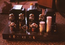
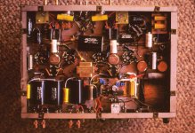
John - beautiful work. You've got a lot going on under the hood!
Chris - thank you for the input. That is what I was thinking as well.
There is one visibly obvious 'problem'. Symmetrically (on both channels), there is a resistor on the 6SN7s that is very charred. So badly that I can't read the specs. The general size/shape/construction is similar to that of the 28.75K 1W resistors.
Apologies for being overly anxious to 'fix.' My quick look at schematic indicates that it may be the 18K 1 Watts (R11/R25 on the schematic) that connect to ground on one side. I'll go back to verify from schematic when I have a moment.
Is this a known failure point or issue?
Cheers,
Ryan
Hi Ryan,
Compare the location of the part with the pictorials in the assembly instructions.
Mine was found in a closet many years ago. Splattered with orange paint and part way through an "audiophile" type rebuild. I stripped everything out and built it according to the original instructions. While building it, I used parts that I knew were better and matched some resistors that should be matched. The first time I turned it on, I couldn't believe the wonderful sound that came out. That's why it hasn't been modified from original yet.
-Chris
Do not use capacitors that are physically too large like in the HF-89 above.
Heh, heh. I did this rebuild years ago in my "bypass capacitor phase". Those large film caps are local B+ bypass caps. Probably would use Genteq 1uF film (the oval ones) for most of that now. The big 50uF Solens (two each in series) was an attempt to try for an Ultrapath connection with a fixed bias amp. Used a diode between them and the 100uF PS caps for isolation.
Things I wouldn't change: star grounding to replace the stock "chassis ground", separate RC strings for each channel after the PS doubling caps, CCS "tail" for the driver stage, triode/ultalinear switches, repurposed stereo/mono switch to enable reduced feedback with triode operation, and a more modern turn-on delay circuit.
That's all moot now anyway. I haven't used that amp in years for anything more than a doorstop.
Hi John,
That's too bad. The HF-87 is one of the better sounding tube amps. Of course, if you continue to stub your toes on it, fire it my way and I'll do the suffering for you.
-Chris
That's too bad. The HF-87 is one of the better sounding tube amps. Of course, if you continue to stub your toes on it, fire it my way and I'll do the suffering for you.

-Chris
The HF-89 cannot compete with my Class A fully differential triode PPP KT-120 transformer coupled mono-blocks using Lundahl amorphous iron in the signal path and Lundahl iron in the PS. CCS cathode "tail" impedance for all stages, including the output, and separate CCS fed active shunt regs. for the input and driver.
Shipping the Eico would probably require building a custom crate. It weighs a ton (output trannies bigger than HF-87). When I bought it on Ebay the seller lived down the road from me on I70 and we met in the middle for the exchange.
Shipping the Eico would probably require building a custom crate. It weighs a ton (output trannies bigger than HF-87). When I bought it on Ebay the seller lived down the road from me on I70 and we met in the middle for the exchange.
Hi John,
So the HF-87 has larger than stock output transformers? The originals were not undersized.
It would ship fine with the tubes yanked. But you are completely right about it being heavy. Heavy cardboard could contain the beast though. A pain to pack of course!
My own HF-87 has gone to Hammond Manufacturing for them to examine the iron for possible replacement. I can't say I'm overjoyed with this, but it was the only way to move forward with a project to build a few new HF-87's done the 2016 way. I'm looking forward to the project, but at the same time I'm worried about my own amplifier. It would also be cool to put two in mono to hear what that does with the PSB speakers.
-Chris
So the HF-87 has larger than stock output transformers?
The HF-89 had larger output trannies that the HF-87. The HF-89 was the fixed bias version of the amp. As I understand it, Eico made more 87's than 89's.
Hi John,
Yes, that's the way I understand things as well. So the HF-87 has stock iron then?
-Chris
Yes, that's the way I understand things as well. So the HF-87 has stock iron then?
-Chris
According to an article published in issue #11 of VTV Eico would normally source iron from either Stancor or Chicago. With the HF-89, according to the article, the output transformers were sourced from another vendor. The article doesn't mention that vendor by name.
- Status
- Not open for further replies.
- Home
- Amplifiers
- Tubes / Valves
- Eico HF-87 refurb


