Hi,
I bought recently Egnater Rebel 30 MKII and it's brilliant except one thing: doesn't have that switch 'Classic/High Gain' like his smaller brother (Rebel 20 MKII).
Could anybody help me with that? In Egnater Tweaker it has been done with switching two resistors, but Rebel MKII is different.
Ideally would be if any owner could check how it is wired up in his amp. I have a few ideas how to do that (mainly inspired by Tweaker) but I prefer to open it and close it just once before next valve replacement and do not drill it for pot or switch (I will stick to the 'classic' all the time probably). Basicaly I would to not experiment 🙂
Many thanks!
 Moved to Instruments and Amps per forum policy.
Post or link to the schematics of both or even either one, otherwise we have no way to assist. The two models may or may not use the same board, and it may not be visually apparent what the changes would be anyway.
Channel
The channel pushbutton switches between the clean/gain channel. That is the same function as the classic/hg toggle switch.
The only real difference between the Rebel 20 and 30 is that the Rebel 30 has reverb for both channels, and the 20 has no reverb. And the use of 6l6/el34 on the 30 and 6v6/el84 on the 20.
Yes for Rebel 20 & 30 it is true, but not for Rebel 20 Mark II and Rebel 30 Mark II.
"The channel pushbutton switches between the clean/gain channel. That is the same function as the classic/hg toggle switch."
It is not the same function. On Classic mode you can still get quite heavy overdrive.
Schematic for Tweaker attached, for Rebel 20 MK II there is no schematic available.
"The channel pushbutton switches between the clean/gain channel. That is the same function as the classic/hg toggle switch."
It is not the same function. On Classic mode you can still get quite heavy overdrive.
Schematic for Tweaker attached, for Rebel 20 MK II there is no schematic available.
Attachments
In Vintage mode R26 and R17 are switched to 0V to knock off some signal level.
In Hot mode caps C19 and C18 are switched in, C19 boosts gain in first triode by bypassing its cathode resistor and C18 knocks off some of the more objectionable high order harmonic distortion products after the 2nd triode.
Should not be too difficult to implement, might even be fun to do it with a 3 position centre OFF switch.
Must try that cascade JFET/MOSFET input stage.
Cheers,
Ian
I understand how it works in Tweaker, I just need to know how it is done in Rebel 20 MKII. Tweaker is just an example.
But thank you for your answer.
But thank you for your answer.
Me too, very interesting circuit, and I think I know what the idea behind it is.Must try that cascade JFET/MOSFET input stage.
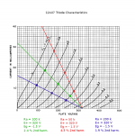
I was tinkering with 12AX7 (valve) load-lines a year or two ago when I realized that a vertical (zero-ohm) load line would cause large amounts of low-order harmonic distortion to be generated by the valve. If there's a zero-ohm anode load, there's no signal voltage on the anode. If there's zero signal voltage on the anode, there's no internal negative feedback due to the mixing of the anode-cathode and grid-cathode electric fields inside the triode.
Ergo, maximum non-linearity. Plot a vertical load line on top of some triode characteristic curves, and you'll see what I mean.
The obvious way to implement a zero (or rather, near-zero) anode load, and still get an output signal from the thing, would be to use a cascode topology. The input triode would be feeding into the very low impedance of the upper triode's cathode.
Obviously this would be a very bad thing for for Hi-Fi, but for a guitar preamp? It was on my list of things to try out some day.
I haven't yet got around to building the cascoded valve arrangement, mainly because you need a pretty high B+ voltage, and then you have to elevate the heater voltage to keep the upper device from exceeding it's heater-cathode insulation breakdown voltage.
But I did confirm that dropping the 12AX7 anode load resistor value in a Fender guitar preamp from 100k to 68k produced a subtle (but audible) improvement in the clean tone. It sounded a bit more "tubey" or "valvey". It's worth further investigation, with a spectrum analyzer this time, to confirm or refute the reality of the idea.
Back to your comment about the Tweaker input stage, to me, the cascode JFET/MOSFET input stage of the Tweaker looks like a solid-state implementation of exactly the same idea. The JFET is feeding into a near-zero load impedance (the source impedance of the MOSFET), so there is virtually no signal swing at the JFET drain, and therefore, maximum square-law nonlinearity in the drain current.
The upper stage (MOSFET) then passes that richly nonlinear (JFET drain) signal current on to a load resistor big enough to generate an output signal voltage that you can pass on to the next stage.
The other interesting thing is that JFETs operate at room temperature (around 300 K), while triodes operate with a cathode at more than three times that temperature (usually 1080 K). That inevitably means much more thermal noise from the valve than from the JFET - roughly 90% more, or about 5.5 dB more!
Additionally to thermal noise, there is also flicker noise, and from what I've read, the flicker noise in a valve input stage dominates at electric guitar frequencies. JFETs have flicker noise too, but some JFETs have very little, compared to a typical triode valve. So, with the right JFET at the input, there may be a quite significant reduction in amplifier input stage noise, compared to the usual 12AX7 valve.
So, as far as I can see, the Tweaker input stage is designed to (a) bring out as much 2nd harmonic distortion from the JFET as possible, making it sound more "tubey" or "valvey", and (b) create much less thermal and flicker noise than a typical 12AX7 input stage would.
So I concur entirely with your comment. Must try that cascade JFET/MOSFET input stage! 🙂
-Gnobuddy
> Ergo, maximum non-linearity.
Analysis may apply to triode (I'd have to think).
Does not apply to the JFET MOSFET cascode.
The JFET has negligible "mixing of the anode-cathode and grid-cathode electric fields inside..."; IOW the Mu is very high, too high to be significant.
The JFET would have significant Square Law distortion. However in the plan in reply #5 there's 1.5K in series with Source. (And an R+C which seems to be not-fitted.) So the JFET is a linear current to voltage converter.
Traditional input stages have gain of 50. If you boost guitar 50X you get around 50V p-p. But JFETs are today only sold to 40V breakdown, and 30V types far more common.
So they hold the JFET Drain at ~~24V and use a common-Gate 400V MOSFET to cascode to the 300V supply rail. The output can swing well over 200V p-p.
The gain is no-more than 100K/1.5K or 66. More like 45 due to loading. Maybe under 30 counting JFET transconductance.
The BIG point in my eye is that tubes always HISS. And worse as their pins tarnish. Hum too. JFETs don't. As I don't think the first stage has a major effect on "tone" (that happens later at higher signal levels" a CLEAN first stage seems to me like a wonderful idea. If we could by a 250V TL072, that would be about as good. We can't, but the JFET+MOSFET may be about the same price and easily integrated into a 360V design.
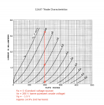
See the attached images I put together while thinking about this. The first image shows a range of plausible resistive anode loads for a 12AX7 stage; next are the extreme cases of near-infinite (CCS) and near-zero (cascode) loads.Analysis may apply to triode (I'd have to think).
Put together, they make a pretty convincing case, no? 🙂
Second-harmonic distortion estimates were made graphically, from the asymmetric lengths of the load line wrt the quiescent operating point (the three dots on each line).
-Gnobuddy
Attachments

You have a solid point. I hate you for it. 😀The JFET would have significant Square Law distortion. However in the plan in reply #5 there's 1.5K in series with Source. (And an R+C which seems to be not-fitted.) So the JFET is a linear current to voltage converter.
Yes, I did figure that part out. I had the same idea quite a while ago, even thought about building it but never did, using a JFET input cascoded with one of the little LND150 MOSFETS in my parts-box.So they hold the JFET Drain at ~~24V and use a common-Gate 400V MOSFET to cascode to the 300V supply rail. The output can swing well over 200V p-p.
I did some back-of-the envelope calculations a while ago, and concluded that an appropriately chosen JFET was the best input stage device for electric guitar. Valves hiss (both thermal and flicker noise), and MOSFETs have lots of flicker noise. JFETs are the sweet-spot for typical electric guitar frequencies and source impedances.The BIG point in my eye is that tubes always HISS. And worse as their pins tarnish. Hum too. JFETs don't.
Good guitar tone is very subjective, but I'm quite sure that there can be audible levels of harmonic distortion generated in the input stage. It doesn't sound like "distortion" the way guitarists use it, but rather as a fatter, more "tubey" clean tone, which is something I really like.As I don't think the first stage has a major effect on "tone" (that happens later at higher signal levels" a CLEAN first stage seems to me like a wonderful idea.
I don't believe in "golden ears", but I also know that I routinely hear some things that most people miss. But I'm also quite sure that plenty of other people with musically sensitive hearing will also hear what I'm hearing.
One data point here: I have a reissue '65 Fender Princeton Reverb. These have one triode gain stage, followed by the usual Fender tone-stack, then the volume control. So, if you turn down the volume of the amp to bedroom level, and keep it there, there is little distortion from all subsequent amplification stages, which are operating at much, much less than their maximum signal excursion levels.
More importantly, if you vary the input level (guitar volume knob, etc), but keep the speaker volume constant using the amp's volume knob, then any changes to distortion you hear must have come from the input stage.
If I play my Squier Standard Strat (which has very low output pickups) through the Princeton Reverb, the sound is squeaky-clean, sounding virtually identical to a solid-state amp with the usual <0.1% distortion.
To confirm, I put a graphic EQ pedal in front of my (solid-state) Acoustic AG30 acoustic guitar amp, and once I dialed in the right EQ curve to match the Fender amp, sure enough, the two amps sounded almost identical with the Squire Standard Stratocaster.
If I play one of my other guitars with hotter pickups into the Princeton Reverb, I can hear additional "tubeyness" appear as the volume control on the guitar goes up. Still very much "clean tone", but with a bit more warmth/shimmer/tubeyness to it. It no longer sounds the same as my solid-state AG-30 acoustic guitar amp, no matter what I do with that graphic EQ.
One other thing to consider, that occurred to me rather recently. The typical 12AX7 guitar preamp stage is biased with the grid about 1.5 volts negative to the cathode. We know that appreciable grid current starts to flow when the grid is still maybe 0.5 volts negative to the cathode; that means grid current starts to flow with less than 1 volt peak signal excursion at the input.
Well, there are plenty of guitar pickups hot enough to spit out 1-volt or more peak signals, particularly at the starting transient of each note. Also, a guitar with a humbucker and 500k volume pot may have a source impedance of more than 125 kilo ohms - high enough that even a small amount of grid current flow will cause some voltage drop (soft clipping).
So I actually suspect that the typical Fender (RCA) 12AX7 input triode stage contributes some soft-clipping to the starting transient from an electric guitar. And I'm sure that the triode nonlinearity produces a small (but audible) amount of smooth, low-order harmonic distortion with many guitar pickups.
I think the 250V TL072 would be really good for the typical piezoelectric ceramic pickup in most electro-acoustic guitars. 🙂If we could by a 250V TL072, that would be about as good. We can't, but the JFET+MOSFET may be about the same price and easily integrated into a 360V design.
Instead, we have some sort of IC opamp running on a 9V battery, trying to cope with a piezo that can potentially spit out voltage spikes of tens of volts. And then we complain about "piezo quack". 😀
-Gnobuddy
OK, I was mistaken. The Rebel 20 is a 1 channel amp. The Rebel 30 is a 2 channel amp. The 30 does have a clean and a gain channel. The Rebel 20 only has a single channel. The new switch on the Rebel 20 mkII is just to switch the level of distortion available, but there is no clean channel. So if you want clean on the Rebel 20 you turn the gain down low and turn the volume up. You can also keep it clean by keeping the power level at tge 20 watts setting.
If you really want a clean channel and a gain channel then you might want to consider the Rebel 30 instead. It will also give you reverb in the amp.
If you really want a clean channel and a gain channel then you might want to consider the Rebel 30 instead. It will also give you reverb in the amp.
Ok, that's nice if I gave you (accidentally) some new ideas to test but do any of you know how switching between classic/high gain in Rebel 20 MKII is done?
I would appreciate any answer relevant in this topic. Tweaker was just for reference.
I would appreciate any answer relevant in this topic. Tweaker was just for reference.
CapnDenny1:
ok, once again from the beginning. I have Rebel 30 MKII. I use both channels. I would like to have the switch 'classic/high gain' (for the overdrive channel only of course) which not only changes the amount of gain but also its shape (turning the gain to a lower level does not give the same effect as switching between 'clasic/high gain').
I had Rebel 20 MKII and there was that switch and I really liked that but I need two channels so I have swapped and paid the difference in the shop.
So my question is:
does anybody know how the switch "classic/high gain" is wired up in the Rebel 20 MKII? I'm asking because I would like to install the same switch in my Rebel 30MKII where I would like to make my overdrive a bit more classic and less aggressive. I really like Rebels and only thing I miss in Rebel 30 MKII is that switch.
This switch as far as I noticed not only changes the amount of gain, it also changes the character of overdrive. It makes it less aggressive, a bit more vintage.
Arni85 - if you can get hold of the schematic, then plenty of people will be able to help.
Without the schematic, unfortunately, only those few people who both own a Rebel 20 Mk II, and have taken it apart to study it, have even a chance of helping.
If I were you, I would focus my efforts on getting that schematic, or at least the relevant part of it.
I found this bit of text in one of the advertisments for the Rebel 20 mk II:
Most modern guitar amps deliberately discard gain at various points in the circuit, for example, by inserting fixed voltage dividers between two gain stages, or leaving a cathode resistor unbypassed. It's likely that the switch you're describing simply reduces the amount of gain that's normally thrown away. But without the schematic, we are just groping in the dark.
If it's utterly impossible to get that schematic, then I would put an overdrive pedal and a graphic EQ pedal in your amps effect loop, and try to dial them in to produce a similar-sounding change in gain, distortion, and EQ when you turn them on. That won't be quite as convenient as a single front-panel switch, but it will at least get you close to your goal, sound-wise.
-Gnobuddy
Without the schematic, unfortunately, only those few people who both own a Rebel 20 Mk II, and have taken it apart to study it, have even a chance of helping.
If I were you, I would focus my efforts on getting that schematic, or at least the relevant part of it.
I found this bit of text in one of the advertisments for the Rebel 20 mk II:
That gives us a general idea what the switch does, but no details. Evidently the Rebel 20 Mk II is a "gainier" amp than the older Rebel 20, and the switch lets you go back and forth between the two versions.CLASSIC/HG switch that selects between Classic Rebel-20 and the new higher gain structure.
Most modern guitar amps deliberately discard gain at various points in the circuit, for example, by inserting fixed voltage dividers between two gain stages, or leaving a cathode resistor unbypassed. It's likely that the switch you're describing simply reduces the amount of gain that's normally thrown away. But without the schematic, we are just groping in the dark.
If it's utterly impossible to get that schematic, then I would put an overdrive pedal and a graphic EQ pedal in your amps effect loop, and try to dial them in to produce a similar-sounding change in gain, distortion, and EQ when you turn them on. That won't be quite as convenient as a single front-panel switch, but it will at least get you close to your goal, sound-wise.
-Gnobuddy
Thank you. I hoped that maybe somebody already did some reverse engineering on Rebel 20MKII.
I will try to get the schematic then.
I will try to get the schematic then.
Hi after a while I did some reverse engineering and I can say that Rebel 30 MKI and MKII seem to have the same preamp. Only difference I suspect is V1 in MKII is TAD 7025WA, but I'm not sure (the idea of MKII version was to increase gain so I think it could be changed). They also had to change some components values but I don't know which ones. I compared my 30watt MKII and 20wat MKI and cathode resistors/caps are the same.
The difference I noticed was that in the schematics part A of the tube is in fact part B, and part B is part A... Don't no why.
To remind the core of my problem: I need the way to add to my Rebel 30 MKII switch 'classic/modern' the same like in Rebel 20 MKII. Rebel 30 has annoying, harsh sound accompanying to the distorted sound all the time. Especially when I don't play very loud or when I play softly, without punching the string.
Schematics:
https://www.elektrotanya.com/egnater_rebel30_sch.pdf/download.html
Attachments
- Status
- Not open for further replies.
- Home
- Live Sound
- Instruments and Amps
- Egnater Rebel 20 MKII - 'classic/high gain' switch - how does it work?