I considering building the Audax HT design CC as a FRONT PAIR. The why, you may ask is that the drivers are all on sale at PE and the CC seems to get rave reviews. So, regardless of the flames resulting from this proposition and questions of good sense, can someone humour me and answer this question:
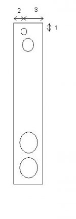
If the drivers and baffle are reorientated as in the attached drawing into a WTMW alignment (the two W's stay in the same spot in the baffle and the baffle dimensions as well as all other box dimensions stay the same), does the speaker response change significantly (i.e. enough to require crossover redesign)? I'm not sure I know all the theory to answer this.
If the drivers and baffle are reorientated as in the attached drawing into a WTMW alignment (the two W's stay in the same spot in the baffle and the baffle dimensions as well as all other box dimensions stay the same), does the speaker response change significantly (i.e. enough to require crossover redesign)? I'm not sure I know all the theory to answer this.
Attachments
The response will hardly change.
The more normal TMWW should be OK too.
In fact the way these are normally built is MTWW to allow
an angled panel at the top to form the midrange enclosure.
🙂 sreten.
The more normal TMWW should be OK too.
In fact the way these are normally built is MTWW to allow
an angled panel at the top to form the midrange enclosure.
🙂 sreten.
Thanks. Drivers are ordered.
I have a follow up question that is related. Since the speakers are to be fronts, I would ideally like to tune the box for more bass extension, yet I'm not ready to delve into a test & measurement rig.
If I reverse-model the response of the woofers in one of the modelling spreadsheets available, then play with the tuning of the box, but still maintaining the same sound level at the crossover point with the mid, can I expect to avoid any crossover mods at all (even padding adjustment)? Once again, the baffle would remain the same.
Thanks.
I've come up with yet another question.
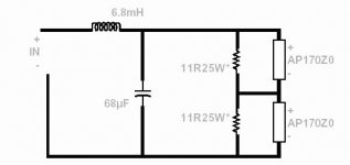
The woofer xover for the design is shown below.
It appears to me that the 2 woofers are padded down significantly to match the efficiency of the mid (87.4 dB for the mid vs 89.3 dB for the woofer, both 6 ohm impedance). I believe the calculation is 2 woofers in series = 92.3 dB efficiency, 12 ohm nominal impedance, and the 22 ohm parallel resistor cuts about 4 dB (I'm not sure how to calculate that).
Can I leave out 1 woofer and recalculate the padding resistor value and also expect minimal impact on sound?
I've come up with yet another question.
The woofer xover for the design is shown below.
It appears to me that the 2 woofers are padded down significantly to match the efficiency of the mid (87.4 dB for the mid vs 89.3 dB for the woofer, both 6 ohm impedance). I believe the calculation is 2 woofers in series = 92.3 dB efficiency, 12 ohm nominal impedance, and the 22 ohm parallel resistor cuts about 4 dB (I'm not sure how to calculate that).
Can I leave out 1 woofer and recalculate the padding resistor value and also expect minimal impact on sound?
Attachments
The woofers are not padded at all in terms of voltage
sensitivity, the impedance is reduced by the resistors.
You could remove one driver and resistor and double
the value of the capacitor and halve the value of the
inductor.
Voltage sensitivity will be the same as the series pair.
Nominal power handling will be halved.
Impedance will be halved.
You'll also need to redesign the enclosure - half volume.
🙂 sreten.
sreten said:Nominal power handling will be halved.
You'll also need to redesign the enclosure - half volume.
Thanks. If power handling is halved, then it's a no-no to me.
I did put the woofer t/s numbers into a box calculator, and it showed me that the box is designed to a BB4 alignment, 48.5Hz tuning, 0 dB peak.
How do I go about optimizing the underdamped response example you gave? In other words, do I fix Qbox at a specific value and juggle others, or Fbox, etc.? I am prepared to play with box volume, but keep the baffle the same.
sreten said:Just omit one port as suggested, 🙂 sreten.
Thanks again. Drivers arrived, crossover components on order.
How about this idea for the enclosure? Will this muck the sound up too much?
Baffle same width, depth 1/2 * design, height 2 * design: all internal volumes same as published design, but it is now a 4 ft tall floorstander. One port omitted as you suggest. TMWW configuration of baffle; T and M at top of baffle, WW at bottom of baffle to get better room gain.
sreten's not around, can anyone else help?
Is my understanding of the theory correct:
1) The effect of lengthening the baffle is minor compared to effect of the baffle width on baffle step loss, so this is minimal impact.
2) The gain/polarity/dispersion effects from driver proximity in the original WTMW layout were not large since the drivers were relatively well spaced, more so than the typical d'Appolito layout.
leadbelly said:
Thanks again. Drivers arrived, crossover components on order.
How about this idea for the enclosure? Will this muck the sound up too much?
Baffle same width, depth 1/2 * design, height 2 * design: all internal volumes same as published design, but it is now a 4 ft tall floorstander. One port omitted as you suggest. TMWW configuration of baffle; T and M at top of baffle, WW at bottom of baffle to get better room gain.
sounds fine to me.
But as a note MTWW is easier because this allows you to simply
add an angled internal section at the top as a midrange enclosure.
Offsetting the drivers (and mirror imaging) will also help matters.
I'd suggest ratio's of 1:2:3 of distances from the centre of the
top driver to the top and the two sides, vertically align the other
driver.
🙂 sreten.
Program?
sreten,
which program did you use for that graphics in this topic???
I'm interested in really good (windows-based if possible) crossover and baffle calculators (simulators?) ...
Nice graph. (what program is it?) 🙂
leadbelly,
I think the best idea is to separate the mid ang high range from the bass section.
My actual system looks like that (twice that, of course, for left and right):
The lower box is a 80x40x50 cm one (80 height, 40 width, 50 deep) built from MDF material, with an inner separating wall in the inside between the two woofers. They're 12" woofers, 4 Ohm each, in series and each has 2 reflex ports with no reflex tube at all (I tried a lot but they just don't need it). Each woofer has an approx. 80 liters of box volume (40x40x50 cm) with that wall inside.
Crossover circuitry is hard wired, no PCB at all or stuff like that. As the crossover schematics show, one inductor and one capacitor have been built in the box inside (they were put on the wall simply).
The upper box is for the smaller 6" midrange and silk tweeter, both 8 Ohms. No openings on the box, completely closed (and damped inside). The rest of the crossover has been put here, too.
The construction is some kind of Bi-Amping/Bi-Wiring although I use one long cable from my Onkyo to the large boxes, and a smaller from here to the small ones.
This is my 6th loudspeaker project and I found this setup to be the best sounding. Deep enormous bass (4 x 12" woofers!), clear and detailed mids and highs. No impedance correction, no additional R,L or C component(s) ... just a simple filter.
They perform very well. For a really strong system I would no more build mid and highs together with the subs, even if they were separated inside. If you are going to build such a strong punchy system suitable for home theater (without subwoofer) too,consider this box design. (filter is your thing..) 🙂
They sound really beautiful.
PS: Notice the 180 degrees phase shift (and therefore the inverted connection) of the midrange.
sreten,
which program did you use for that graphics in this topic???
I'm interested in really good (windows-based if possible) crossover and baffle calculators (simulators?) ...
Nice graph. (what program is it?) 🙂
leadbelly,
I think the best idea is to separate the mid ang high range from the bass section.
My actual system looks like that (twice that, of course, for left and right):
An externally hosted image should be here but it was not working when we last tested it.
The lower box is a 80x40x50 cm one (80 height, 40 width, 50 deep) built from MDF material, with an inner separating wall in the inside between the two woofers. They're 12" woofers, 4 Ohm each, in series and each has 2 reflex ports with no reflex tube at all (I tried a lot but they just don't need it). Each woofer has an approx. 80 liters of box volume (40x40x50 cm) with that wall inside.
Crossover circuitry is hard wired, no PCB at all or stuff like that. As the crossover schematics show, one inductor and one capacitor have been built in the box inside (they were put on the wall simply).
The upper box is for the smaller 6" midrange and silk tweeter, both 8 Ohms. No openings on the box, completely closed (and damped inside). The rest of the crossover has been put here, too.
The construction is some kind of Bi-Amping/Bi-Wiring although I use one long cable from my Onkyo to the large boxes, and a smaller from here to the small ones.
This is my 6th loudspeaker project and I found this setup to be the best sounding. Deep enormous bass (4 x 12" woofers!), clear and detailed mids and highs. No impedance correction, no additional R,L or C component(s) ... just a simple filter.
They perform very well. For a really strong system I would no more build mid and highs together with the subs, even if they were separated inside. If you are going to build such a strong punchy system suitable for home theater (without subwoofer) too,consider this box design. (filter is your thing..) 🙂
They sound really beautiful.
PS: Notice the 180 degrees phase shift (and therefore the inverted connection) of the midrange.
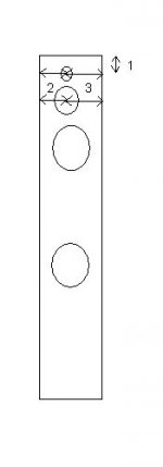
sreten said:Offsetting the drivers (and mirror imaging) will also help matters.
I'd suggest ratio's of 1:2:3 of distances from the centre of the
top driver to the top and the two sides, vertically align the other
driver.
Thanks.
Like this?
Attachments
leadbelly said:Thanks. Like this?
Yes for the tweeters, but mids directly below tweeter.
But I've got to say no for the bass unit placement.
(You'll get too much mid bass)
One driver should be directly below the mid unit.
The other midway between this and the floor.
This will give much smoother room gain and reduce floor dip.
which program did you use for that graphics in this topic???
WinISDbeta available as freeware. Save image as
bitmap and convert to a GIF using windows Paint.
🙂 sreten.
Re: Program?
I can't see how your crossovers can possibly work correctly without Zobel correction of the bass and mid units.
And having done this you'll find your target loads will be nearer to 6 ohms than 8 ohms.
A Linkwitz / Riley 2nd order crossover is much better than a Butterworth alignment.
Baffle step compensation is not accounted for in the crossover design.
🙂 sreten.
Vortex said:No impedance correction, no additional R,L or C component(s) ... just a simple filter.
I can't see how your crossovers can possibly work correctly without Zobel correction of the bass and mid units.
And having done this you'll find your target loads will be nearer to 6 ohms than 8 ohms.
A Linkwitz / Riley 2nd order crossover is much better than a Butterworth alignment.
Baffle step compensation is not accounted for in the crossover design.
🙂 sreten.
sreten said:Yes for the tweeters, but mids directly below tweeter.
But I've got to say no for the bass unit placement.
(You'll get too much mid bass)
One driver should be directly below the mid unit.
The other midway between this and the floor.
Like this?
Attachments
- Status
- Not open for further replies.
- Home
- Loudspeakers
- Multi-Way
- effect of reorientating baffle and drivers?