I've been playing around for some time trying to find the best way to mount (or not) my DML panels. Recently I've noticed that using the wavelet spectrogram in REW gives an interesting perspective. The wavelet spectrogram reveals some things about the time domain response that the regular frequency response does not. (Thanks @homeswinghome) In particular, it seems to be pretty good at identifying which frequencies continue to reverberate (i.e. ring) long after the signal has stopped.
Below are the wavelet spectrograms for the same plate mounted three different ways. The plate is a sandwich composite with carbon fiber/epoxy skins (0.25 mm) and balsa core (1.6 mm) that is approximately 406 mm x 584 mm.
In the first case, the panel was suspended from wires attached to the panel along the top of the long side, at about 130 mm from either end. This condition roughly approximates a free boundary condition.
In the second case the panel was mounted to a rigid wood frame using squares of a 3M double sided tape (about 12 x 12 mm) spaced about every 50-75 mm around the entire perimeter. This 3M tape is called 3M Indoor Mounting Tape and is about 1.5 mm thick with adhesive on both sides. I believe the foam substrate is a closed cell polyethylene. This foam is quite easy to compress, and rebounds quickly when you stop squeezing. This condition rougly approximates a simply supported boundary condition.
In the third case the panel was mounted to the same frame, but this time with continuous strips of EPDM rubber, about 10 mm thick and 20 mm wide. The strips ran nearly the length of all four sides with the exception of about 50-75 mm from each of the four corners. This foam is still soft (though not as soft as the 3M) and rebounds more slowly than the 3M tape. This condition also roughly approximates a simply supported boundary, but with a bit more constraint than the previous condition, and hence slightly higher natural frequencies.
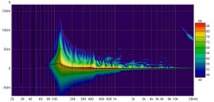
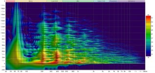
Here are the REW wavelet spectrograms for each of the three mountings (1/6 Frequency resolution):
Wires
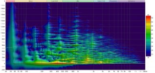
3M Indoor Foam
EPDM Foam
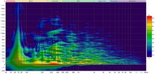
Note that with the "Wires" suspension, there are a large number of vertical lines in the spectrogram, indicating a large number of natural frequencies that continue resonating (ringing) long after the original signal. This I would consider not to be a good thing. Also note, however, that the SPL level of these resonances is relatively low in comparison to the initial signal.
With the 3M Indoor foam mounting, there are fewer long resonating frequencies. But wow, some of them (like at 200 and 400 Hz) ring with an SPL similar to the initial signal. Probably also not a good thing. Maybe even a worse thing than the Wires mounting.
On the other hand, with the EPDM continuous mounting, the only clearly resonating frequency is the fundamental. This, I believe, is a good thing. I feel pretty sure that the reason for the difference is the damping effect provided by the EPDM foam compared to the PE foam and the free edges.
Is anybody else using the wavelet spectrogram to evaluate their DMLs?
Eric
Below are the wavelet spectrograms for the same plate mounted three different ways. The plate is a sandwich composite with carbon fiber/epoxy skins (0.25 mm) and balsa core (1.6 mm) that is approximately 406 mm x 584 mm.
In the first case, the panel was suspended from wires attached to the panel along the top of the long side, at about 130 mm from either end. This condition roughly approximates a free boundary condition.
In the second case the panel was mounted to a rigid wood frame using squares of a 3M double sided tape (about 12 x 12 mm) spaced about every 50-75 mm around the entire perimeter. This 3M tape is called 3M Indoor Mounting Tape and is about 1.5 mm thick with adhesive on both sides. I believe the foam substrate is a closed cell polyethylene. This foam is quite easy to compress, and rebounds quickly when you stop squeezing. This condition rougly approximates a simply supported boundary condition.
In the third case the panel was mounted to the same frame, but this time with continuous strips of EPDM rubber, about 10 mm thick and 20 mm wide. The strips ran nearly the length of all four sides with the exception of about 50-75 mm from each of the four corners. This foam is still soft (though not as soft as the 3M) and rebounds more slowly than the 3M tape. This condition also roughly approximates a simply supported boundary, but with a bit more constraint than the previous condition, and hence slightly higher natural frequencies.
Here are the REW wavelet spectrograms for each of the three mountings (1/6 Frequency resolution):
Wires

3M Indoor Foam

EPDM Foam

Note that with the "Wires" suspension, there are a large number of vertical lines in the spectrogram, indicating a large number of natural frequencies that continue resonating (ringing) long after the original signal. This I would consider not to be a good thing. Also note, however, that the SPL level of these resonances is relatively low in comparison to the initial signal.
With the 3M Indoor foam mounting, there are fewer long resonating frequencies. But wow, some of them (like at 200 and 400 Hz) ring with an SPL similar to the initial signal. Probably also not a good thing. Maybe even a worse thing than the Wires mounting.
On the other hand, with the EPDM continuous mounting, the only clearly resonating frequency is the fundamental. This, I believe, is a good thing. I feel pretty sure that the reason for the difference is the damping effect provided by the EPDM foam compared to the PE foam and the free edges.
Is anybody else using the wavelet spectrogram to evaluate their DMLs?
Eric
Hello Eric,Is anybody else using the wavelet spectrogram to evaluate their DMLs?
Eric
Thank's for this new thread.
Do you have a ranking of those 3 panels from subjective tests?
The wires seems to have more long resonances
The 3M, less but strong resonances at for example 200 and 400Hz (red portion)
The EPDM seems more controlled. Too?
What might be interesting here is to get the experience of other wavelet spectrogram users and to make the relation with our auditory system. What is too long for the auditory system according to the frequency ?
By the way, I am pretty sure my panels have such behavior, probably not like the "wires" as I find them subjectively highly dynamic.
In the main DML thread, we should find one of my post where I open the hypothesis of a limitation in the bass for the DML linked to the decay time. See #6683
Christian
"Is anybody else using the wavelet spectrogram to evaluate their DMLs?"
I will be now. Thank you for opening this thread Eric.
I will be now. Thank you for opening this thread Eric.
Not yet using wavelet but will do! It seems to be a powerfull tool to continue the effort to reduce reflections from the edges!
Note about EPDM from wikipedia, EPDM is made from ethylene, propylene, and a dienecomonomer that enables crosslinking via sulfur vulcanization and has functional rubbery properties only when crosslinked. Sulfur vulcanization is a chemical process for converting natural rubber or related polymers into materials of varying hardness, elasticity, and mechanical durability by heating them with sulfur[1] or sulfur-containing compounds.
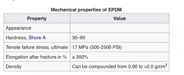
It all means that there i a huge number of different ”EPDM” material to chose from, shore is one value to look for. I have tried two different variants weather sealing from tesa moll and and an epdm foam used for lining ponds. There is a difference in how soft they are tesamoll is softer. It is clearly less ringing with tesa moll.
I have also tried the two other methods scotch (all around the edges) and lines both rings a lot.
Thomas
Note about EPDM from wikipedia, EPDM is made from ethylene, propylene, and a dienecomonomer that enables crosslinking via sulfur vulcanization and has functional rubbery properties only when crosslinked. Sulfur vulcanization is a chemical process for converting natural rubber or related polymers into materials of varying hardness, elasticity, and mechanical durability by heating them with sulfur[1] or sulfur-containing compounds.

It all means that there i a huge number of different ”EPDM” material to chose from, shore is one value to look for. I have tried two different variants weather sealing from tesa moll and and an epdm foam used for lining ponds. There is a difference in how soft they are tesamoll is softer. It is clearly less ringing with tesa moll.
I have also tried the two other methods scotch (all around the edges) and lines both rings a lot.
Thomas
I'd think you'd need to match the characteristic impedance of the panel material with the surround. Such that when the bending wave hits the panel edge, it's absorbed without reflecting anything back into the panel. I think this happens at the transition between a speaker cone edge and the suspension also. From the web "Sorbothane turns mechanical energy into heat. As the material is deformed, molecular friction generates heat." Perhaps with just the right shore and thickness, when the wave hits the edge, it appears to the panel as if it just keeps going. Like a coaxial cable terminated in its characteristic impedance, vs short (clamped) or open (free).
Nice measurements and info! From what i recall from the bibliography, a damped boundary gives the most smooth bass response. With 1.5 mm width the 3M frame doesn't seem to be able to damp to much.
So, apparently, there is also this ringing advantage with such boundary conditions 🙂
So, apparently, there is also this ringing advantage with such boundary conditions 🙂
Last edited:
Thomas,It all means that there i a huge number of different ”EPDM” material to chose from, shore is one value to look for. I have tried two different variants weather sealing from tesa moll and and an epdm foam used for lining ponds. There is a difference in how soft they are tesamoll is softer. It is clearly less ringing with tesa moll.
I have also tried the two other methods scotch (all around the edges) and lines both rings a lot.
Thomas
No doubt you are right that there are almost infinite variations of EPDM. I'll have to take a look at tesa moll for sure.
I don't understand your last sentence, can you explain a little more, even if it didn't work?
Eric
Thanks. Right, the 3M Indoor foam really rings. But don't count out 3M mounting tape products. I have also used a product call 3M Extreme (a mounting tape for exterior use), which seems to perform similarly to the EPDM (low ringing). Which is better (EPDM or 3M Extreme) seems to depend on the panel.Nice measurements and info! From what i recall from the bibliography, a damped boundary gives the most smooth bass response. With 1.5 mm width the 3M frame doesn't seem to be able to damp to much.
So, apparently, there is also this ringing advantage with such boundary conditions 🙂
Eric
That looks really good. I'll have to try outdoor measurements some time. I can't seem to work up the motivation to lug it all out!Found some old measurements on my small speakers. Diaphragm is 2 mm balsa core with CF skins 0,15mm in total 2,3mm it's 190x250mm surrounded by EPDM foam "tesamoll weather seal". and mounted to a solid frame. The measurements are done outdoors.
Tried the wavelet feature.
View attachment 1131893View attachment 1131894View attachment 1131906
Eric
I think you are exactly correct about the matching impedance of the surround with the panel. But is there a way to do that other than completely by trial and error? I think (maybe) one could estimate the panel impedance with the infinite panel approximation. But how does one estimate the impedance of a boundary condition? Ideas anyone?I'd think you'd need to match the characteristic impedance of the panel material with the surround. Such that when the bending wave hits the panel edge, it's absorbed without reflecting anything back into the panel. I think this happens at the transition between a speaker cone edge and the suspension also. From the web "Sorbothane turns mechanical energy into heat. As the material is deformed, molecular friction generates heat." Perhaps with just the right shore and thickness, when the wave hits the edge, it appears to the panel as if it just keeps going. Like a coaxial cable terminated in its characteristic impedance, vs short (clamped) or open (free).
Eric
I use for example classical piano music when I listen. To me it is very revealing if there is any ringing in the system. I used two sets of speakers with different material at the edges when I was testing so I could do instant A-B testing.I did a lot of testing of different solutions/material cotton fabric, strings and all sort of rubber/plastic foam I could get my hand on. In the end of I decided on epdm tesamoll As the best.Thomas,
No doubt you are right that there are almost infinite variations of EPDM. I'll have to take a look at tesa moll for sure.
I don't understand your last sentence, can you explain a little more, even if it didn't work?
Eric
I look for the following for damping
1. High density
2. High plasticity
3. High adhesive tack ( I think this quality is important to ensure energy transfer)
4. Depth no less than 10mm
5. Contact width no less than 20mm and preferably more.
I have had the best results with a very soft dense elastomer used as sound absorbing mats for hard drives. It has a very soft 'fleshy' feel to it. You can get these as pads and then cut them into strips but unfortunately elastomer is expensive.
If that is too expensive, and for the larger panel I prefer it can be, a foam can work providing it is dense and has the plasticity and high tack.
Burnt
Eric this might be helpful?I think you are exactly correct about the matching impedance of the surround with the panel. But is there a way to do that other than completely by trial and error? I think (maybe) one could estimate the panel impedance with the infinite panel approximation. But how does one estimate the impedance of a boundary condition? Ideas anyone?
Eric
The impedance equation is: Z=sqrt(E/ρω),
where E is the elastic stiffness of the plate, ρ is the mass per unit area of the plate, and ω is the angular frequency of the excitation. This equation can be used to determine the impedance mismatch between the plate and the elastomeric material by calculating the ratio between the elastic stiffness of the plate and the mass per unit area of the elastomeric material.You have an optimal match when the ratio is 1
This implies the ratio needs to be matched for each frequency for perfect termination but I think it’s safe to assume a bandwidth with an optimal termination at a midpoint frequency with a decaying performance either side of this midpoint. This suggests that with a range of damping materials with differing E might mop up a wide bandwidth.
Burnt
Hello BurntEric this might be helpful?
The impedance equation is: Z=sqrt(E/ρω),
where E is the elastic stiffness of the plate, ρ is the mass per unit area of the plate, and ω is the angular frequency of the excitation. This equation can be used to determine the impedance mismatch between the plate and the elastomeric material by calculating the ratio between the elastic stiffness of the plate and the mass per unit area of the elastomeric material.You have an optimal match when the ratio is 1
This implies the ratio needs to be matched for each frequency for perfect termination but I think it’s safe to assume a bandwidth with an optimal termination at a midpoint frequency with a decaying performance either side of this midpoint. This suggests that with a range of damping materials with differing E might mop up a wide bandwidth.
Burnt
Could you detail a bit more please, I don't understand for now what you are pointing and that sounds like an interesting novelty here?
More in detail :
- impedance equation : I know for now only the impedance at the driving point of an infinite plate which is 8.sqrt(B.µ), resistive not frequency dependent. Which impedance do you show here?
- I like the idea with different E if we refer to the information of different materials in the suspension of the Gobel panel.
Hi Christian,
I was looking for a formulas that would match impedance between a plate of material vibrating at a known frequency and an elastomer damper at the perimeter. I was having some trouble finding it but GPT3 found the one I shared. It seems a logical proposition that we might match the impedance using the elastic stiffness of the plate with varying the density of the elastomers used to meet the various frequencies. I could be wildly wrong but it seems logical so I thought I would share it as a thought.
Burnt
Hi Burnt,Hi Christian,
I was looking for a formulas that would match impedance between a plate of material vibrating at a known frequency and an elastomer damper at the perimeter. I was having some trouble finding it but GPT3 found the one I shared. It seems a logical proposition that we might match the impedance using the elastic stiffness of the plate with varying the density of the elastomers used to meet the various frequencies. I could be wildly wrong but it seems logical so I thought I would share it as a thought.
Burnt
I appreciate the suggestion and perhaps there is something to it. But one thing that bothers me is that it seems clear that the impedance of the boundary will depend on the width and thickness, as your list of criteria implies. But the equation: Z=sqrt(E/ρω) does not include any such dependence. So it feels like there must be more to it than that.
Eric
BurntHi Christian,
I was looking for a formulas that would match impedance between a plate of material vibrating at a known frequency and an elastomer damper at the perimeter. I was having some trouble finding it but GPT3 found the one I shared. It seems a logical proposition that we might match the impedance using the elastic stiffness of the plate with varying the density of the elastomers used to meet the various frequencies. I could be wildly wrong but it seems logical so I thought I would share it as a thought.
Burnt
I fully agree on goal. On that topic we face 2 difficulties : what is the panel impedance at the edge? what is the impedance of a surrounding material (see Eric's recent post).
GPT3 is ?
I agree with the above, I am looking for the right starting point as well. However, I am not sure why the impedance at the edge should be different from any point on the panel. It has more degrees of freedom to move for sure but the material elasticity does not change and that appears to be the key to matching. Very happy to learn I am wrong.
GPT3 is the OpenAI AI that is proving to be a much better search tool than Google and can do far more than just search e.g. it can write code for you from a text description
Burnt
GPT3 is the OpenAI AI that is proving to be a much better search tool than Google and can do far more than just search e.g. it can write code for you from a text description
Burnt
I'm just guessing here, but i imagine you still have an sort of infinite impedance on the edge. Thats what determines the natural frecuencies (which also depend on the material properties), which are related to the dimensions of the panel --> the reflections on the edges. I imagine its like a tube with absorbant material in the closed end. Part of the energy, in this case of a mechanical wave, is absorbed by damping. Since the reflections are not absolute (the impedance is not infinite anymore, tho, really big), there are neither lines of 0 displacement, nor peaks in the same amplitude (resonances are damped), which results in a smother response.Burnt
I fully agree on goal. On that topic we face 2 difficulties : what is the panel impedance at the edge? what is the impedance of a surrounding material (see Eric's recent post).
GPT3 is ?
I don't recall a paper putting some differential equation which expression varies in relation to boundary conditions. Maybe COMSOL may help there.
- Home
- Loudspeakers
- Full Range
- Effect of Boundary Conditions on the Ringing of DML Speaker Panels
