Hello everybody,
This is my first post here but i read this site for many months. I’m an enthusiast DIY-er but with no knowledge of designing schemes. I wonder if you could help me.
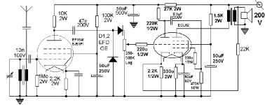
I want to build something simple with tubes, just for fun, a radio retro in 20’s style. I have parts from an old pick-up Tesla Suprafon: exit transf, a couple of ECL82 – russian equivalents, a penthode EF184 and power transf. with ~165 V c.a. for anodic and 6.3 V for filaments.
I have two possibilities:
a) 1V2 – EF184-germanium diode-ECL82 or
b) 1V2 – 1’st (L)82 as rf. ampli.-1’st (C)82-tide as a diode for detection-2’nd ECL82 as AAF.
Audio power no more than 1W.
Can anybody help me and do the design?
I’m not a rich tube guy but I can share with you some pictures of a 50 years old german marvel – Strassfurt 600 - http://www.elforum.ro/viewtopic.php?t=26263
Thanks in advance!🙂
Please excuse my bad English!
This is my first post here but i read this site for many months. I’m an enthusiast DIY-er but with no knowledge of designing schemes. I wonder if you could help me.
I want to build something simple with tubes, just for fun, a radio retro in 20’s style. I have parts from an old pick-up Tesla Suprafon: exit transf, a couple of ECL82 – russian equivalents, a penthode EF184 and power transf. with ~165 V c.a. for anodic and 6.3 V for filaments.
I have two possibilities:
a) 1V2 – EF184-germanium diode-ECL82 or
b) 1V2 – 1’st (L)82 as rf. ampli.-1’st (C)82-tide as a diode for detection-2’nd ECL82 as AAF.
Audio power no more than 1W.
Can anybody help me and do the design?
I’m not a rich tube guy but I can share with you some pictures of a 50 years old german marvel – Strassfurt 600 - http://www.elforum.ro/viewtopic.php?t=26263
Thanks in advance!🙂
Please excuse my bad English!
There are a couple of things you may want to try.
I think you need to put a low pass filter between the detector diode and the volume control, other wise the output stage is amplifying pulsating RF rather than just audio. Try 1 meg resistor and 1nF capacitor in parallel from diode to ground, then coupled to the top of the voulume control with a .01uF capacitor.
If you are in the mood for experimentation, you might want to try to put in an AVC circuit to keep the output level. To do this dont use the diode connected to ground, reverse the direction of the other diode, and add another low pass filter by connecting for example 33K resistor from the top of the volume control, to a 100pF capacitor going to ground. Connect the junction of the resistor and capacitor to the grid of the EF184. I dont know anything about the EF184, so I dont know if this will work, or it the R and C values are suitable, but it is something you could experiment with.
Thank you!
Thank you for sharing your knowledge.
Info about EF184 here:
http://www.r-type.org/exhib/aai0086.htm
Thank you for sharing your knowledge.
Info about EF184 here:
http://www.r-type.org/exhib/aai0086.htm
TRF receiver
Hi Michael,
It's likely that the RF section will oscillate due to it's high gain and layout factors.
The selectivity (the bandwidth when tuned) will be very wide, causing several stations to be received at the same time. The bandwidth is defined entirely by the Q of the tuning circuit.
The circuit values look rather random, but something might happen!
Best have a look for some better RF circuit. Try a search for "Regenerative TRF"
Here's a page with some: http://www.mines.uidaho.edu/~glowbugs/regens.htm
Good luck,
- Status
- Not open for further replies.