This is my testing of two ECM8000's.
Magnepan MG10.1, test amp, M-Audio MobilePre. 1m distance, roughly 2/3m height. Non-gated, 1/3 Octave smoothing.
The image below shows the vertical orientation mic 1 versus 2, the lower traces are the horizontal mic 1 versus 2.
Magnepan MG10.1, test amp, M-Audio MobilePre. 1m distance, roughly 2/3m height. Non-gated, 1/3 Octave smoothing.
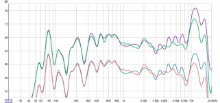
The image below shows the vertical orientation mic 1 versus 2, the lower traces are the horizontal mic 1 versus 2.
Attachments
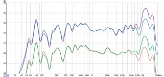
My conclusions are that the two mics are pretty good up to 2kHz or so.
You can see an obvious deviation.
As for horizontal versus vertical, there's a clear difference, although not too much.
In my case, I am trying to design a notch filter / crossover for the top octaves, so 4dB separation is a really big deal.
I'm going to try some measurements near-field on a BG Neo3PDR to see if the trends continue.
Very interesting.....
Thanks for the good work. There is more difference than I would have expected.
Thanks for the good work. There is more difference than I would have expected.
I'm going to try nearfield measurements of the tweeter ribbon tonight.
Instead of calibration, I may use that as a reference and consider it "flat" and calibrate my own mic from there.
I'm also going to try and eliminate as many variables as possible:
Try two amps
Try a different mic cable
Try a different driver/speaker
I may end up paying for a calibration, but what I don't want to have happen is me to do that and still have issues because the soundcard or some other piece of methodology (like the orientation) was screwing it up!
arc2v said:
I may end up paying for a calibration, but what I don't want to have happen is me to do that and still have issues because the soundcard or some other piece of methodology (like the orientation) was screwing it up!
That's easy to correct for; just have the SC play into itself and look at the response. You can even look at the output including the amp this way, although you'll need to take care to not overload the input to the SC.
I'd be pretty suprised if a modern SC/amp aren't pretty close to ruler-flat even near the extremes of their rated ranges though.
[edit: w00t, mailman just delivered a motherlode of teeny leetle microphone capsules. It's gonna be a fun weekend fellas.]
Yeah, I don't think that's the problem, but I need to be sure. I had another thread here where I calibrated my amp and SC -- both turned out pretty well after I zoomed out the scale (the default scale made them look awful, but it was only over a 4dB range).
I have also read the the MobilePre has a noisy mic preamp section and is a bit weak on the phantom power voltage. That may affect the mic response, but measure flat when you do the loop-back. Sadly there's no way to test that, other than to reference.
I have a friend with a Behr. Xenyx 802 that I may use for phantom power and preamp duties and see if the FR changes. Hopefully it will not, but I will post the results, nonetheless.
Here's the amp calibration by itself:
http://www.diyaudio.com/forums/attachment.php?s=&postid=1442490&stamp=1204313721
That's from my previous thread.
http://www.diyaudio.com/forums/attachment.php?s=&postid=1442490&stamp=1204313721
That's from my previous thread.
arc2v said:Here's the amp calibration by itself:
http://www.diyaudio.com/forums/attachment.php?s=&postid=1442490&stamp=1204313721
That's from my previous thread.
I'm really surprised you have so much rolloff at the edges. High impedence input,,,? Sound card...?
Also, what's with the crazy phase? Was this not measured electrically? There shouldn't be so much delay in a direct input->output measurement...
I wish I knew. Car audio amp powered by 12V,10A power supply. m-audio MobilePre soundcard.
Amp output goes through a 16:1 voltage divider so that it won't blow the inputs of the soundcard. The voltage divider changes the effective impedance so that it is 1/10 the soundcard input impedance (3550 Ohms)
That's why I'm trying to eliminate all these variables. If I can just get it down to the mic calibration, or know for sure that my amp or soundcard is junk, then I can fix it. It's the not-knowing-and-guessing game that is frustrating me.
More data!
Semi-nearfield (14 to 16", 3' off the floor), MG10.1. 4 sweep average per position, 4 random positions. I would take one measurement and then move the stand in no particular direction about an inch. This was to see what effect positional variance had on the overall response.
Also, I ran baseline nearfield tests and got similar results, except you could see the phase cancellation. Moving back helped smooth this out. I did, though test my cable and ran tests with reference channel of both the sound card and the amplifier. All overlayed perfectly, meaning my amp or the mic cable I made is not causing any major errors. I tested the cable by literally holding the MobilePre onto the back of the mic during the test. I'm glad the cable wasn't at fault for anything because I really prefer to be seated during all the tests 🙂
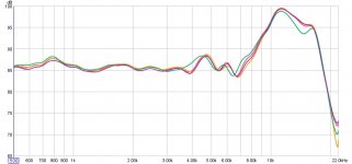
Anyway, back to the results. First chart is the four sweeps at different positions for the horizontal mic.
Some variance with position, but overall you can see the important trends.
Small peak at 4500Hz, Dip at 6800 Hz, Big peak at 12000 Hz and then finally rolling off steep at 18000 Hz. Remarkably flat up to almost 4k!
Semi-nearfield (14 to 16", 3' off the floor), MG10.1. 4 sweep average per position, 4 random positions. I would take one measurement and then move the stand in no particular direction about an inch. This was to see what effect positional variance had on the overall response.
Also, I ran baseline nearfield tests and got similar results, except you could see the phase cancellation. Moving back helped smooth this out. I did, though test my cable and ran tests with reference channel of both the sound card and the amplifier. All overlayed perfectly, meaning my amp or the mic cable I made is not causing any major errors. I tested the cable by literally holding the MobilePre onto the back of the mic during the test. I'm glad the cable wasn't at fault for anything because I really prefer to be seated during all the tests 🙂
Anyway, back to the results. First chart is the four sweeps at different positions for the horizontal mic.
Some variance with position, but overall you can see the important trends.
Small peak at 4500Hz, Dip at 6800 Hz, Big peak at 12000 Hz and then finally rolling off steep at 18000 Hz. Remarkably flat up to almost 4k!
Attachments
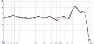
Here's the same test, but with the mic vertical. Again, four random positions all less than an inch apart. 4 sweep average for noise reduction.
Again, flat to 4kHz, a small plateau up at 6k to 7k, big hump at 12k-13k, and then the final roll-off at 18k or so.
Overall, in the vertical orientation the mic seems to have a flatter response to 7k with a much less pronounced peak.
Again, flat to 4kHz, a small plateau up at 6k to 7k, big hump at 12k-13k, and then the final roll-off at 18k or so.
Overall, in the vertical orientation the mic seems to have a flatter response to 7k with a much less pronounced peak.
Attachments
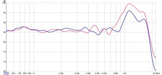
Finally, a representative sample from each overlayed for comparison.
Up to 4k, identical, or close enough for home-testing. But clearly the hump is of different magnitude and bandwidth when the mic is horizontal (red is horizontal, blue is vertical)
Neither of these is even close to any "standard" cal file I've seen floating out there.
D'Appolito talks about this in p54 of "Testing Loudspeakers". He predicts the "hump" in the response, but also mentions that true free-field mics control the resonance and damping to achieve a flatter response.
Obviously whatever is in my mic isn't working 😀
I made cal files for my mic using these measurements. Granted, it makes a big assumption that my Magnepan's are flat from 1k on up -- but as a worst case, I'll be designing any speakers I build to their FR -- not exactly a bad target response 🙂
Eventually I'll spring for a thorough calibration but for now, I think this will work.
Thanks again for all the help and support. I think the final step for me is to open up the mic (without destroying it) to see what the electronics inside look like. I'll snap some pics if I do.
Attachments
arc2V,
I also found my ECM8000 is pretty flat up until about 3KHz - then you get a 1dB rise until about 5KHz then it varies. I get a double hump around the 12-15KHz range. I'll post my calibration file tonight just for comparison.
You are heading down the same path I am.... that is us a consistent tweeter and "divide out" the response between your measurement, and someone else who has measured the same tweeter with a calibrated mic.
Another alternative is to use manufacturers published data. People will say "but unless you know the measurement conditions / baffle size" - well that's fine below about 3KHz where the size of your typical HiFi speaker baffle will cause diffraction ripple. Above that it isn't significant and room gating becomes less of an issue.
I will publish a page on my site to the above effect as a cheap way of getting some sort of calibration where you canno justify the cost to do get it done professionally.
David.
I also read somewhere (can't find it now) that the ECM8000 changes FR if the phantom power is low.
The mic will run off 15V, but it changes the FR - IIRC.
The mic will run off 15V, but it changes the FR - IIRC.
I found this schematic online. I don't know about the op-amp / transistor setup there to say if the voltage would affect anything.
But that's a lot of junk in there for a capsule that is supposed to just need 9V and some signal leads. 🙂
Maybe someone else here can chime in on what those sections do. It looks like a filter/compensation network, but I'm better with passive LCR circuits, not semiconductors.
But that's a lot of junk in there for a capsule that is supposed to just need 9V and some signal leads. 🙂
Maybe someone else here can chime in on what those sections do. It looks like a filter/compensation network, but I'm better with passive LCR circuits, not semiconductors.
Attachments
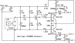
That's a simple circuit! The two PNP transistors provide a current-source feed to the Zener diode (D1) from the phantom ppower common-mode dc feed on the XLR connector.
What is surprising is that if D1 really is only 6V, then the mic capsule is being fed with only about 200uA. (Even if the FET in the capsule was short-circuit, only 6V/15k (400uA) will be flowing. Most mic capsules tend to be supplied at a higher bias current than this. Also, if D1 is 6V, then you wouldn't expect any change in the mic parameters once you got to a feed voltage where the zener had started to conduct and regulate the mic dc feed, so why the characteristics should change with 15V phantom feed compared with 30V (say) isn't obvious.
What is surprising is that if D1 really is only 6V, then the mic capsule is being fed with only about 200uA. (Even if the FET in the capsule was short-circuit, only 6V/15k (400uA) will be flowing. Most mic capsules tend to be supplied at a higher bias current than this. Also, if D1 is 6V, then you wouldn't expect any change in the mic parameters once you got to a feed voltage where the zener had started to conduct and regulate the mic dc feed, so why the characteristics should change with 15V phantom feed compared with 30V (say) isn't obvious.
I wasn't quite sure how you meant that "simple circuit" comment so I'll clarify 😀
The posted circuit looks needlessly complicated.
Similar DIY mics using the same capsules usually consist of a capsule, battery, and signal leads. -- That's the simple circuit!
So I was wondering what all the extra junk in there is for.
Also, does the 16V on that capacitor/zener section in the top left corner mean that it has 16V through it, or that it has to be rated for 16V, or maybe 16V is the zener trigger voltage? I don't know, that's why I'm asking.
Ouroboros said:why the characteristics should change with 15V phantom feed compared with 30V (say) isn't obvious.
I should think that they wouldn't and that's part of the point.... do you have some information that they do change with varying phantom?
Considering that if this is a panasonic capsule variant or workalike, Panasonic's app note says it should be fed with 1.5v through a 2.2k resistor, which is only 680uA...
The recommended Linkwitz circuit [after mod] shows 9v and 10k.
I can always try increasing the bias on one of my 'scratch monkies' here and see what happens... Go to a 8.1v zener and smaller resistor (will the rest of the circuit need to be rebiased too? Actually, just reducing the bias current resistor seems less fraught with consequences)
But first... since I don't entirely grok the circuit... Spice.
Earlier in the thread some-one else commented that they had heard that the characteristics change with supply voltage.
Arc2v. The complication is due to providing a balanced output when phantom-powered. A non-balanced output mic is a trivial circuit, but this ECM8000 one isn't exactly complicated. It is only a single transistor gain stage with an emitter-follower after it. The (balanced) emitter follower is also the current limiter for the Zener diode dc feed.
Arc2v. The complication is due to providing a balanced output when phantom-powered. A non-balanced output mic is a trivial circuit, but this ECM8000 one isn't exactly complicated. It is only a single transistor gain stage with an emitter-follower after it. The (balanced) emitter follower is also the current limiter for the Zener diode dc feed.
- Status
- Not open for further replies.
- Home
- Loudspeakers
- Multi-Way
- ECM8000 Orientation for Speaker Measurements