Alright I was bored and I'm persistant. I successfully removed the suspect shown above and it measures defective. Then I re-measured the other one the board and it looked funny so I removed it too. It is defective also. These are marked CB. I then checked the two on the other channels which are marked AC and found that one of those is defective. Mouser does't have BCX68-10, but has BCX6824TA or does it have BCX51-10, but has BCX5110,115. Are those the same thing? And is there something else I should checking?
I don't know how they're being used so I can't suggest a substitute. You should remove them from the circuit to confirm that they're actually defective.
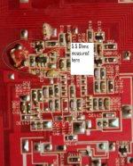
I have removed the two CB and the two AC and confirmed that both CB are defective and only one AC is defective.
If you notice the resistor in the pic above it has seen a lot of heat. If fact all four of them have, but removing them from the circuit they measure ok. One of them I could still see enough color bands to tell they are 220 ohms. I replaced them anyway.
Two of the over heated resistors are between the the +Rail and the CB collector. I think the other two over heated resistors are between the -Rail and the AC collector. These are in the pathes you suggested earlier to find out why we aren't seeing the proper +/- on the op amps.
I'll have to email Eclipse to see if they might provide a schematic.
Yes.
The emitter of the transistor labeled CB is connected to Pin #7 V+ of that channel's op amp.
The emitter of the transistor lableled AB is connected to Pin #4 V- of thant channel's op amp.
The emitter of the transistor labeled CB is connected to Pin #7 V+ of that channel's op amp.
The emitter of the transistor lableled AB is connected to Pin #4 V- of thant channel's op amp.
If they're being used as regulators, they're not critical components. Any transistor that's the same size and has an equal or higher current and voltage rating should work.
You should check the Zener diodes connected to their bases. They may have been damaged when the transistors failed.
You should check the Zener diodes connected to their bases. They may have been damaged when the transistors failed.
Checking the Zener diodes in the circuit, they all measure ~1.5K ohms and rise as they charge a cap. Seem like those will be ok?
As a side note: Eclipse responded that they can no longer provide schematics since they no longer do business with the supplier of their amplifiers.
As a side note: Eclipse responded that they can no longer provide schematics since they no longer do business with the supplier of their amplifiers.
Check them with the meter set to diode check. Does it read ~0.7vwith the red probe on the anode?
Is it's possible that the Zeners are marked 8V?
Fairchild and Vishay have 15v Zeners with an 8V mark. They are 15v Zeners which is what I'd expect to see in the regulators.
Fairchild and Vishay have 15v Zeners with an 8V mark. They are 15v Zeners which is what I'd expect to see in the regulators.
I'm not sure if this is very helpful, but the PCB reminds me off older Infinity (UFO-shaped Kappas) or JBL (GTQ360 i.e.) amps.
Just that this one is red...
Perhaps the GTQ360 will be essentially the same.
The service manual for the smaller GTQ240 is available at eserviceinfo.com
Perhaps this helps!
/edit: At least it was designed by the same guy: http://www.apsdc.com/Manny Experience.htm
Perhaps you can send him a mail!
Just that this one is red...
Perhaps the GTQ360 will be essentially the same.
The service manual for the smaller GTQ240 is available at eserviceinfo.com
Perhaps this helps!
/edit: At least it was designed by the same guy: http://www.apsdc.com/Manny Experience.htm
Perhaps you can send him a mail!
Last edited:
8V makes more sense because the dimensions I measured on them are SOT-23 dim. The referece I have to markings list the BV as SOT-323 which is slightly smaller than what I have, plus I thought 30V was too high also.
Thanks for the intel gisewhcs. I'll have a look at that service manual later on today. I had seen Manny's website, but I figured I was too "small potatos" for him to respond to my needs, so I have not tried to email him.
New parts arrived today.
I ordered BCX6825TA to replace the original transistors marked CB. The new ones are marked CD.
I ordered BCX51-10115 to replace the original transistors marked AC. The new ones are marked AC also.
I ordered MMBZ5245B-V to replace the zeners marked 8V.
I installed the new parts and even replaced the ones that appeared to be ok in order to be uniform across the four channels. I think I have made progress, although not as much as I had hoped for.
The amp now cycles on and off. While it does this I do get audio on the front pair of channels while the amp is in the brief "on" state.
The rear channels pulse DC while the amp is cycling on and off.
Originally, it was the Left Rear channel that had shorted outputs when I got it.
The first thing I did was replace both Left and Right rear outputs before discovering there was more problems going on and then asking for help.
SO..... my next questions are, is there a next step and if so what is it?
Remove the outputs from the left rear channel. Does that allow the other 3 channels work properly.
I was using two speakers at a time to check this earlier.
So when I went back to check for the pulsing on the rear set now that the outputs are removed, I wired one speaker in and then checked - it did. I wired the other one in and rechecked it - they did not. The amp stays on with two speakers wired to the rear channels. The outputs are still removed. It also required that both be wired up, it can't be one or the other, has to be both. These are 8 ohm speakers.
I have another 4 ohm speaker, so I wired it in bridged to the front channels while the other two are on the rear, and the amp stays on and plays out the front in mono and has now for about 10+ minutes.
Something to note is that when I turn on the front low pass filter and touch the low pass crossover adjustment, I get bad hum. I do not get the hum either off or high pass turned on.
- Status
- Not open for further replies.
- Home
- General Interest
- Car Audio
- Eclipse 3241