I have been reading the forums here to see if I can resolve my problem with out assistance, but I have to ask for some professional help.
When I got this amp I started by checking for shorted FETS, rectifiers, outputs, drivers and pre-drivers since a prior posting for this very model seemed to point that direction. What I found was one pair of TIP35C & TIP36C shorted on one channel. Once I found those I pulled the drivers, pre-drivers, and emmitter resistors for the blown channel off the board to check them out of the circuit but found them all to be ok. I remounted the components I removed and installed a new pair of outputs. I checked for continuity from the center of the coils to the input shields and to the non-bridging outputs and that is good. With nothing else glaring I powered it up with 5 amp fuse and a 3ohm resistor in-line with the B+.
This amp has DC on the outputs measured without signal cables & speakers attached as follows
RR -25.280VDC
LR 25.320VDC
LF -25.280VDC
RF 25.320VDC
It draws almost 2 amps at start up but settles down to 1.012A. I noticed that the power LED starts off bright like its good to go, but dims after it settles down to the 1A draw but it is not blowing fuses. This amp does not have a diagnostic set of LEDs unless the dimming of the one is just that.
I tested for audio output using an 8 ohm resistor in parallel with an 8 ohm speaker. The LR & RR have a very tiny audible signal that you have to put your ear up to the speaker to hear with the gain at maximum sensitivty and the volume all the way up on the source. The RF & LF have nothing. I fear that there is something wrong with the surface mounted components on this one.
This amp uses the 318D but I don't know what the expected signals should be on each pin.
Sorry for the long post, I am new here.
Rich
If I understand your question correctly;
With one 8 ohm resistor accross the Left Rear outputs its beginning current draw was 1.7xxA and climbed to 2.110A and held steady there. Also as a note the LED did NOT dim this time.
For curriosity I placed another 8 ohm resistor accross the Right Front outputs also and it caused no change to the above measurements.
I think there may be an error somewhere. If you have 25+v across the speaker terminals of any channel, the current draw would be significantly more than 2 amps. Measure the DC voltage directly across the speaker terminals for each channel.
Thats a good point. The ~25V was across the speaker terminals no load. Measuring it across the installed 8 Ohm resistors it is ~5VDC and then ~15V on the other no load terminals.
Yes it is.
With the 3 ohm resistor still inline I have 14VDC at the power terminals.
Without the 8 ohm resistors on the speaker terminals it drops to ~11V when turned on.
With the 8 ohm resistors on the speaker terminals, it drops to ~7V when turned on.
With the 3 ohm resistor still inline I have 14VDC at the power terminals.
Without the 8 ohm resistors on the speaker terminals it drops to ~11V when turned on.
With the 8 ohm resistors on the speaker terminals, it drops to ~7V when turned on.
Do you have both positive AND negative voltage on the power supply terminals of all of the op-amps in the amp?
No, removing the 8 ohm resistors from the output terminals I measured the following between the non-bridging speaker terminals and pins #4 & #7:
Right Rear 318D
Pin #7 +12.20V
Pin #4 +.855V
Left Rear 318D
Pin #7 +12.25V
Pin #4 +.854V
Right Front 318D
Pin #7 -7.10V
Pin #4 -13.82V
Left Front 318D
Pin #7 -7.08
Pin #4 -13.80
Right Rear 318D
Pin #7 +12.20V
Pin #4 +.855V
Left Rear 318D
Pin #7 +12.25V
Pin #4 +.854V
Right Front 318D
Pin #7 -7.10V
Pin #4 -13.82V
Left Front 318D
Pin #7 -7.08
Pin #4 -13.80
Do you get the same readings if you place the black probe on one of the non-bridging speaker terminals?
It's strange that some have the proper positive voltage while others have the proper negative voltage. Can you post a photo of the onside of the amp?
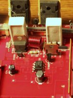
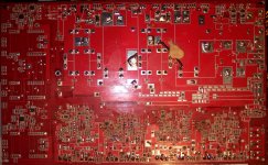
These were taken just before replacing the shorted outputs. The two pictures may not be of the same top and bottom circuit. The original pictures are too large to upload so these are cropped down.
Attachments

Can you post a wide shot showing the entire board? If they're too large to post, please email them to me.
babin_perry@yahoo.com
babin_perry@yahoo.com
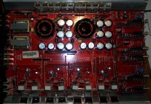
With the amp powered up, what's the DC voltage from the agnd of one transformer to the agnd of the other transformer?
With the black probe on the agnd of the left transformer (as shown in above pic) I get .1mV across them.
Follow the power supply lines back from the op-amps to see if they go to the same point (possibly through resistors) or if they go to dedicated Zener diodes.
I am giving up on this amp. I followed both the V- and V+ for all four of the op amps and could only find one area that measures suspect. Q115C and R19C measure low ohms but that doesn't explain to me why none of the four channels work. I did not find opens or shorts in those paths on the other three. Plus I don't have the proper tools to replace surface mount components, so I would just destroy this further.
Perry thank you for your help.
Rich
Perry thank you for your help.
Rich
- Status
- Not open for further replies.
- Home
- General Interest
- Car Audio
- Eclipse 3241