I built my first tube amplifier based on this schematic:
Single Tube amplifier
The amp powers on and I hear a subtly audible hum from the speaker that I would atribute to the power supply and heater wires.
I''m not getting any audi out, just a slight "hissing" sound.
I've modified the schematic below - I currently have the audio input from the pot with a 220k resistor in series and no ground. I'm thinking this is the issue, but not sure.
5W_ECL82_SE_amplifier | Zack Fedor | Flickr
Using a Triad R-23B power transformer
5k 8ohm output transformer from China (nice one though)
8 ohm speaker
USSR 6Mb8 tube, tested strong
1N4001 diodes on the rectifier
All componenets either new or in perfect working condition
I would appreciate any input 🙂
Please post the exact schematic diagram of the specific circuit that you are trying to fix.
Measure and post the DC voltages at all of the circuit nodes.
Measure and post the DC voltages at all of the circuit nodes.
Last edited:
Resistors in series with the grids (pin 1 and pin 3) have a 220 ohm value, not 220K. The potentiometer must have all 3 terminals connected, follow the first schematic.
If that schematic is indeed what you built be very careful as it is NOT an isolated power supply. The shock hazard is very high and with out a safety ground it could kill you.
Without a signal ground your input signal has no reference and and can't drive the grid of the input tube.
I would strongly suggest building an isolated power supply. then you can safely provide an input ground and the circuit may work just fine.
Without a signal ground your input signal has no reference and and can't drive the grid of the input tube.
I would strongly suggest building an isolated power supply. then you can safely provide an input ground and the circuit may work just fine.
The second schematic PSU part is totally wrong.
If mains connected as described, it's dangerous, somebody would be die.
The HV capacitors "negative" connected to secondary AC?
The ECL82 filament connected also to secondary AC?
If mains connected as described, it's dangerous, somebody would be die.
The HV capacitors "negative" connected to secondary AC?
The ECL82 filament connected also to secondary AC?
Thank you for your reply.
This is the current Schematic:
5W_ECL82_SE_amplifierv1 | Zack Fedor | Flickr
As for DC voltage, I wrote my measurments last time I checked, Ill try to find the paper or check again.
This is the current Schematic:
5W_ECL82_SE_amplifierv1 | Zack Fedor | Flickr
As for DC voltage, I wrote my measurments last time I checked, Ill try to find the paper or check again.
Resistors in series with the grids (pin 1 and pin 3) have a 220 ohm value, not 220K. The potentiometer must have all 3 terminals connected, follow the first schematic.
Thank you for your reply.
I'll check the resistor value and replace if neccesary. Or, should I wire a 20nf cap in series with a 10m resistor to gnd instead?
The potentiometer is correct, I just didnt put all 3 pins in this schematic (I got lazy and it was originally only meant for me anyway) but I'll fix it.
Thank you very much! That was an idea I was thinking of implemeting, but wasn't sure. I'll make sure it doesn't happen 🙂
It currently, (I hope) has a 220R resistor in series to the grid. I may have installed a 220k by mistake, I will check tonight.
It currently, (I hope) has a 220R resistor in series to the grid. I may have installed a 220k by mistake, I will check tonight.
This is the current Schematic:
5W_ECL82_SE_amplifierv1 | Zack Fedor | Flickr
Stop right here. This is a hot chassis design, very dangerous, and discussion is not even allowed on DIYaudio. Don't even plug this in. Please.
Chris
Sorry for the confusion.
It seems I made some errors in the schematic that aren't present in the amp.
I was trying to clean up this Single Tube amplifier schematic a bit.
The amp:
IMG_2823 | Zack Fedor | Flickr
IMG_2819 | Zack Fedor | Flickr
You can't see much as it's a pretty cramped chassis, but it will give some kind of idea as to the construction. The diodes where isolated with cable jacketing after the photo and before testing.
This is the schematic as it sits. I confirmed visually with the amp.
5W ECL82 Class-A Mono Amplifier | Zack Fedor | Flickr
Safety concerns have been noted by members, as the PSU is not isolated.
I am considering rebuilding this amplifier to be safer. Maybe an ECL82 pre-amp with something like a Class-A transistor, or maybe class-d power amp. Let me know if this sounds like a decent idea.
I'm using a Dayton Audio ND65-8 2-1/2" 8Ω 5w speaker in a small ported box and it sounds great, even with the Class-D amp I tested it on.
Speaker: IMG_0270 | Zack Fedor | Flickr
The amplifier is for a Crosley 52tf radio shell I've been restoring for my wife (thus the safety concern).
Last edited:
Do you have any knowledge of electronics?
Seeing the drawings I doubt it. :-(
High voltage is dangerous, not recommended for unpractised beginners.
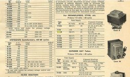
BTW you wrote, that have Triad R-23B transformer.
It's a 115V primary, 250V CT 22mA, 6.3V 0.8A and 12.6V 0.6A transformer.
Is this in this amplifier?
Seeing the drawings I doubt it. :-(
High voltage is dangerous, not recommended for unpractised beginners.
BTW you wrote, that have Triad R-23B transformer.
It's a 115V primary, 250V CT 22mA, 6.3V 0.8A and 12.6V 0.6A transformer.
Is this in this amplifier?
I work repair low voltage equipment professionally. I don't often work with AC, alothough I have studied it (and know how not to die). This is mt first AC PSU and it is with a Triad transformer from 1968. I have a tendancy to more advanced first projects, as opposed to easy ones.
I fixed the transformer section which was borrowed from another scheamatic.
Look at the schematic again.
I fixed the transformer section which was borrowed from another scheamatic.
Look at the schematic again.
Last edited:
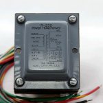
Before the Triad R23-B cover was painted:
IMG_1753 | Zack Fedor | Flickr
Chassis, before it was cleaned up and some componenets isolated:
IMG_2819 | Zack Fedor | Flickr
I'll take a current photo.
I work on PCB boards. This is my first point-to-point project.
Unpracticed beginners work? Maybe.
IMG_1753 | Zack Fedor | Flickr
Chassis, before it was cleaned up and some componenets isolated:
IMG_2819 | Zack Fedor | Flickr
I'll take a current photo.
I work on PCB boards. This is my first point-to-point project.
Unpracticed beginners work? Maybe.
Rather seems like 250-0-250 (500V CT)BTW you wrote, that have Triad R-23B transformer.
250V CT 22mA
Is the high voltage winding's center tap connected to anything?I fixed the transformer section which was borrowed from another scheamatic.
Look at the schematic again.
UPD: BTW, 1N4001s, being rated at 50V, are not appropiate for this application. Use something rated at 1000V or more (1N4007 or whatever).
Last edited:
You are correct about the cenetr tap.
The center tap is red-yel and it's not connected to anything....Ah, should be gnd. :facepalm
The center tap is red-yel and it's not connected to anything....Ah, should be gnd. :facepalm
Last edited:
Might be, I've only found a couple of bad transformer photos 😀250CT in Triad datasheet.
Should be grounded. AND REPLACE THE DIODES TO APPROPRIATE ONES BEFORE POWERING ON!The center tap is red-yel and it's not connected to anything.
It has 1N4007 diodes as per the Schematic.
The carrying capacity is 1A, which seems low.
Should I swap them for 1N5408 diodes or something else?
The carrying capacity is 1A, which seems low.
Should I swap them for 1N5408 diodes or something else?
- Home
- Amplifiers
- Tubes / Valves
- ECL82 Class-A amp - No sound