Thank you very much for your answers.
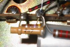
The colours of the feedback resistor (in pararel with the 2n7 condenser) are: Yellow/Purple/Black/Silver (47 ohm in theory) I have measured it and I read 135 Ohm at the meter . Strange ¿Isn't it?.
I can't find the grid leak resistor... Maybe I have spend too many hours this weekend with it and my eyes can not concentrate anymore. I think I better leave it for today
Take care
The colours of the feedback resistor (in pararel with the 2n7 condenser) are: Yellow/Purple/Black/Silver (47 ohm in theory) I have measured it and I read 135 Ohm at the meter . Strange
¿Isn't it?. I can't find the grid leak resistor... Maybe I have spend too many hours this weekend with it and my eyes can not concentrate anymore. I think I better leave it for today
Take care
Attachments
Hi,
A problem it is not...
But, if you want the best channel separation then don't use this configuration.
Crosstalk can occur due to layout and also within the tube...
This is why twin tubes with symmetrical internal layout often image so well.
If you have an internal shield such as with the cascode tubes like the ECC88s, grounding it als improves matters greatly.
Cheers,😉
No problem.
A problem it is not...
But, if you want the best channel separation then don't use this configuration.
Crosstalk can occur due to layout and also within the tube...
This is why twin tubes with symmetrical internal layout often image so well.
If you have an internal shield such as with the cascode tubes like the ECC88s, grounding it als improves matters greatly.
Cheers,😉
Hi,
Not really..You can't measure resistance with a cap across it.
Un solder the cap at one end and measure again.
Cheers,😉
Strange ¿Isn't it?.
Not really..You can't measure resistance with a cap across it.
Un solder the cap at one end and measure again.
Cheers,😉
You can't measure resistance with a cap across it.
Yeah, that's the price I paid for spending all the weekend with this beauty antique while my wife was away. At the end of the day I did stupid things


The value of this feedback resistor is really low comparing with all the schematics I've seen so far, but the truth is that the amp sounds very nice. ¿Do you recommend experimenting with higher values?.
Next weekend I will change the couplig capacitors to 100nF Ruby Orange. Then I will study the possible reforms to the pre-amp.

Cheers
Hi,
47R for a NFB resistor is something I have a hard time believing. I have doubt it is the FB resistor.
If the amp sounds fine as is, why not leave it as it is?
Sant Pere...Costa Brava, right?
Expect to see me there in a few years, I intend to buy a hacienda there....
I'll be spending a year or two learning Catalan.
Buena suerte y buena nid,😉
Paco.
The value of this feedback resistor is really low comparing with all the schematics I've seen so far, but the truth is that the amp sounds very nice.
47R for a NFB resistor is something I have a hard time believing. I have doubt it is the FB resistor.
If the amp sounds fine as is, why not leave it as it is?
Sant Pere...Costa Brava, right?
Expect to see me there in a few years, I intend to buy a hacienda there....
I'll be spending a year or two learning Catalan.
Buena suerte y buena nid,😉
Paco.
Hi Frank,
If you move here you will find this valve's shop in Barcelona:
http://www.amptek-es.com
This weekend I'll go to there to buy the caps and the Alps pot to enhace my new old amp.
About the valve for the pre-amp, they don't have the E80CC that you mention, but they do have E82CC and E88CC. ¿Wich one is recomended?. Here is the list of models they have available:
http://www.amptek-es.com/previo.html
Hasta luego.
You could first check if you really need the tube. Try connecting a CDP directly to the power amplifier with a pot between to see if it's sensitive enough.
Else, go for the standard 12AU7A/ECC82 they have.
Else, go for the standard 12AU7A/ECC82 they have.
Hi,
Does your preamp require gain or is it just a control center?
If you don't need the gain I'd recommend the White Cathode Follower as a buffer.
Cheers,😉
P.S. I'm no big fan of the ECC82/12AU7A.
but they do have E82CC and E88CC. ¿Wich one is recomended?. Here is the list of models they have available:
Does your preamp require gain or is it just a control center?
If you don't need the gain I'd recommend the White Cathode Follower as a buffer.
Cheers,😉
P.S. I'm no big fan of the ECC82/12AU7A.
Jax, I've connected the output of the Nad C-521 direct to the power stage (through the 100K alps) and the sound is ¡crystal clear!  😎 So I will think about the preamp in the future. Now I will try to take the maximum performance of the power stage.
I've already replaced the 22K caps with Ruby 100K.
I have tried a NFB resistor of 10K and the gain rises a lot, but the tone is not as "clear" as with the 47 Ohm resistor (the high frequencies don't have "presence"). So now It looks fine with 120 Ohm.
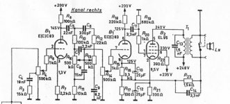
I measure 250 V at the plates of the p.p. pentodes, 127 V at the second triode, 40V at the plate of the first triode..... I still haven't received the Morgan Jones book, so I don't know how to calculate the optimum bias, re-disign it to run in Class A... 😀 😀 ¿what's wrong with Amazon.com? It takes too long
😎 So I will think about the preamp in the future. Now I will try to take the maximum performance of the power stage. I've already replaced the 22K caps with Ruby 100K.
I have tried a NFB resistor of 10K and the gain rises a lot, but the tone is not as "clear" as with the 47 Ohm resistor (the high frequencies don't have "presence"). So now It looks fine with 120 Ohm.
I measure 250 V at the plates of the p.p. pentodes, 127 V at the second triode, 40V at the plate of the first triode.....
I still haven't received the Morgan Jones book, so I don't know how to calculate the optimum bias, re-disign it to run in Class A... 😀 😀 ¿what's wrong with Amazon.com? It takes too long When you have tried the feedback resistor of 10k did you also change the value of the capacitor in parallel with it ? That would explain the absence of presence at higher frequency's.
Don't forget the dominant pole (3k3+470p) when you lower the feedback. It will rob the uppers 😉
As Sjef says, you will have to change the 2n7 also. Try removing it while you experiment with the feedback. Or at least keep the product of the resistor and capacitor constant.
As Sjef says, you will have to change the 2n7 also. Try removing it while you experiment with the feedback. Or at least keep the product of the resistor and capacitor constant.
The very low feedback resistor is probably right for the period, when huge amounts of feedback was popular. That way is was possible to use smaller output transformers and still get very deep bass from an amp. My first tube project was a Philips stereo from 1964, take a look at the 1k5 feedback R and the same kind of split cathode resistor in the attached schematics.
fdegrove said:Hi,
Not really..You can't measure resistance with a cap across it.
Un solder the cap at one end and measure again.
Cheers,😉
No!!!...why not?
Is perfectly possible to measure a resistence with a ceramic cap across it!!😉
In the schematic of Manuel Guerrero amplifier he have not designed the connection to ground of the output transformer secundary...so when he mesure the feedback resistance he mesure the feedback resistor in parallel with the 180 Ohms resistor (via ground).
Not surprisingly it find 135 Ohms...the 180 in parallel with 470 Ohms, the feedback resistor!!🙂
Yellow.purple.brown.silver..😉
Time to study
Nope, but I will do it. Of course: R+C=
I have find this interesting link to feed my humble knowledge (while the book arrives):
Introduction to Electron Tubes
Cheers
When you have tried the feedback resistor of 10k did you also change the value of the capacitor in parallel with it ?
Nope, but I will do it. Of course: R+C=
I have find this interesting link to feed my humble knowledge (while the book arrives):
Introduction to Electron Tubes
Cheers
Re: Time to study
Hi Manuel!
When you took the fedback resistor out of circuit and change it for the 10k ...you have not measured it??
Saludos! 😉
pingfloid said:
Nope, but I will do it. Of course:
Hi Manuel!
When you took the fedback resistor out of circuit and change it for the 10k ...you have not measured it??
Saludos! 😉
pingfloid said:40V at the plate of the first triode.....
Hi
40 Volts is too low!...Have you used a high impedance voltimeter?
If yes the 100 uF capacitor in paralel with R1- 2,2K must be leaking...change the capacitor!
And check also if R1 and R3 are out of specs.
Horrible experiment
I have rewired one channel the Majestic ECL82 pp amp according to this schematic:
http://www.bonavolta.ch/hobby/en/audio/ecl82_3.htm
The result is awful: it begins to oscilate and motorboat like a mad thing. 😡
If I remove the nfb resistor the oscilation stops, but the sound is very bad.
I've triple-checked all the conections, and because I have the Rainer Zur Linde's book, I have followed all the indications.
¿What do you think that can be wrong? ¿Any other test that I can do appart of remofving the nfb resistor?
Thank you
positive feedback
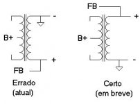
My guess is that you're applying positive feedback.
To solve: invert the secondary of the OPT, i.e. the (-) end you applied to ground must be positive (the one on which you will connect the FB resistor). The (+) end, on which you're attaching the FB resistor now, must go to groundlevel.
I hope my explanation doesn't confund you more.
Maybe a picture says more.
My picture is wrong, showing a PP trafo. However, the secondary connections apply to SE to. So, don't look at the primary, just the secondary.
Attachments
Yes, that's it! Thank youy very much!
I did keep the original connection for the primary, but in this new design it has to be reversed.
The sound is much better than the original schematic. (I can compare since I did modify only one channel) so now I will update both channels with the Zur Linde's design.
No more worries about the 47 Ohm resistor at the feedback of the original design 🙄
Cheers! 🙂
- Status
- Not open for further replies.
- Home
- Amplifiers
- Tubes / Valves
- ECL 82 low power end tube