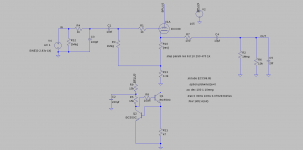
I am struggling a little with this schematic, something is wrong with the schematic (or the model) below and I cant figure out what.
When I increase the R10 using the res variable, as R10 increases, the quotient current starts dropping, not a little but a lot. With values of R10 = 10R - 15ma; 250R - 7ma; 470R - 4.8ma, 1k - 2.7ma. Of course due to this, the distortion numbers also go worse as R10 rises. Vgk rises correctly though as R10 rises.
The current calculations also don't look correct, with 3.3k and 105v supply, I should get about 31ma, but I get half of that, about 15ma. It looks like R13 is not controlling the current, but R10 is. Reducing R13 drastically doesn't seem to increase the current in proportion, R10 = 470 and R13 = 1k gives about 5ma of current.
The tube model is the ayumi model, I took it from this link (second last post) - http://www.diyaudio.com/forums/tubes-valves/243950-vacuum-tube-spice-models-40.html#post3863379
Attachments
Last edited:
No, you should get about 15mA with zero bias, because the internal beam resistance of the ECC88 is about 3.3k.The current calculations also don't look correct, with 3.3k and 105v supply, I should get about 31ma, but I get half of that, about 15ma.
Correct. That is how it is supposed to be. You need to learn to draw load lines.... For example, with R10 = 470R:It looks like R13 is not controlling the current, but R10 is.
An externally hosted image should be here but it was not working when we last tested it.
Last edited:
R10 is the cathode resistor and that controls the current because the grid gets its negative bias from it.
Your HT is 105V so you probably want to aim for about 50V at the cathode. With R13 at 3.3K that gives a cathode current of about 15mA. YOu palt/cathode voltage is about 55V. Looking at the datasheet, 15mA plate current at 55V plate.cathode voltage require a grid voltage of close to zero. If you change R13 to 6.8K the cathode current becomes 7.5mA which requires a grid voltage of about 1V which you should get with R10 set to about 110 ohms.
Cheers
Ian
Cheers
Ian
If you go for the zero grid bias option you should expect to get significant grid current. If your source is beefy then this is not a significant issue, however if your volume pot is exposed to this grid current then you should expect it to degrade rapidly.
Personally i think something like the ECC99 or 5687 would perform the function far better and allow for a sensible grid bias point.
Zero grid bias has its roll because it produces low output impedance and even gain down to DC, but it is best applied as a second stage in a DC coupled circuit with a beefy front end.
Shoog
[FONT=Courier New, monospace]Thanks guys, that helped clarify a lot of things. I am yet to get a transformer, so the B+ is not fixed yet. I plan to use a 110v step down transformer with a shunt regulated supply, so I would say that a max B+ of about 130-135v. Though if I get a lot better results with higher voltage, I wont mind going for it.
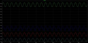
[/FONT][FONT=Courier New, monospace]I tried to scan a lot of combinations in ltspice to get the best distortion numbers . Whatever values I tried, I get good THD values of ballpark about 0.007-0.01. This is with a ccs (ring of two or current source of ltspice). The 2nd harmonic is about -75db and the third is better than -125db. Is that the best that this tube can do. I get lower distortion values than this if I use a Vgk of about 0.1v, but then the grid current will start flowing at these values (how much grid current?).[/FONT] [FONT=Courier New, monospace]
It also seems to favor high values of Vgk (except for 0.1v) irrespective of the angle of the loadline. i.e. distortion will be getting worse with Vgk of 0.1, 4, 3, 2, 1.5, 1. For some of these low distortion combinations, loadline has a less than 90 degree angle.[/FONT] [FONT=Courier New, monospace]
If I use a negative supply and apply external bias using a trimpot so that the cathode is sitting at ground, how much variations in the dc offset can I expect, just want some rough idea about this.
[/FONT]
Attachments
Do you mean "can I remove the output coupling capacitor?"If I use a negative supply and apply external bias using a trimpot so that the cathode is sitting at ground, how much variations in the dc offset can I expect,
If so the answer is no, you will always need the output coupling capacitor; the output offset will not be reliable or stable (unless you used a bias servo).
Spice is not very good at predicting distortion. Rarely if ever does practice agree with simulation in this respect. Spice can easily be 50%b out. Distortion in triodes is directly proportional to output level so the figures you mention need to be qualified by the output level before anyone can say if they are the best that can be done. Distortion in triodes is also very dependent on plate/cathode voltage - bigger voltages give less distortion. Distortion in triodes also depends on input level and bias point and how close you are to grid current so larger Vgk voltages tend to lead to lower distortion.
Cheers
Ian
Cheers
Ian

Looks about the best you will get and keeps you reasonably well away from grid current territory.
Shoog
Shoog
There should be absolutely to need to use DC heaters in a line level ECC88 preamplifier. Twisted AC heaters is more than adequate.How good is LM317 for the heater supply, looking at the datasheet Figure 15, it doesnt inspire a lot of confidence. Ripple Rejection is down to almost -50db at 10hz itself.
Shoog
The LM317 is good enough for the main power rail in thousands of professional audio products. It is certainly good enough for a heater supply.How good is LM317 for the heater supply, looking at the datasheet Figure 15, it doesnt inspire a lot of confidence. Ripple Rejection is down to almost -50db at 10hz itself.
There should be absolutely to need to use DC heaters in a line level ECC88 preamplifier. Twisted AC heaters is more than adequate.
Shoog
What rating transformer should I order to get a 6.3V supply. A 6.3V 1A and a 6.3V 2A transformers will probably give different voltages at 300ma current draw. Please also specify the same thing for 12.6v also as I plan to get transformer that supports both. What happens when mains voltage fluctuates by 10%. The voltage vary in the range of about 5.7-7.0v
AC heater voltages can be +/- 10% so this should be the least of your concerns in India. Figure out your heater demands then double it. If you are only drawing 300mA then the 1A supply should be ok.
Is this "preamp" just a cathode follower buffer? You realize there will be no gain..
Is this "preamp" just a cathode follower buffer? You realize there will be no gain..
I am trying to do heater elevation for this and had a few questions. My B+ is 135v, Iq – 10ma, Vg – 2v. With a ccs, cathode sits at about 30 odd volts and with a resistor(4.7k) instead of the ccs, it sits at about 40 odd volts. As per the datasheet for ecc88, max Vh-k is 50v and max Rh-k is 20kR. I need to do a voltage divider between B+ and GND and a cap from midpoint to ground. The midpoint (say 68v with equal voltage divider) will connect to one end of the heater supply. I plan to have a 2w resistor on the other leg of the heater supply in case I need to drop some voltage. Do I need a voltage divider for heater supply also? How do I calculate the heater to cathode resistance so that its below the 20k limit.
😕 Please explain.The midpoint (say 68v with equal voltage divider) will connect to one end of the heater supply.
Do I need a voltage divider for heater supply also?
Basically it is Rk plus the lower resistor in your divider. But this limit is a 'soft' limit; I wouldn't worry too much about keeping it below 20k. Use 10k resistors in your divider and you will be OK.How do I calculate the heater to cathode resistance so that its below the 20k limit.
In the 6.3VAC lines, can I connect any of these to the voltage divider on HT, or do I need to find 3.15v point and connect that to the HT divider. I guess since its just a reference, any should be ok.😕 Please explain.
Basically it is Rk plus the lower resistor in your divider. But this limit is a 'soft' limit; I wouldn't worry too much about keeping it below 20k. Use 10k resistors in your divider and you will be OK.
So in this design, it will be 200+4.7k+R2 < 20k, where R2 is the bottom resistor of the divider. How does this work with a ccs, where there is no explicit resistor...
If both resistors are 10k, that gives me about 6.75ma on 135v, kinda high, which makes the dissipation about 0.9W per resistor. So I will need to use 5W resistors for this. I will probably push both to about 15k and use 2w resistors with 0.6W dissipation for each, as you say, its a soft limit.
I have seen some people use high voltage B+ in similar designs and use large resistor (15-20k) on the cathode. That would leave hardly any margin for R2. How is heater elevation managed in those. I will try to dig up some post for this.
If it's a DC heater supply then any point will do. If it's an AC heater supply then it is usually beneficial to use the electrical centre point, to reduce hum.In the 6.3VAC lines, can I connect any of these to the voltage divider on HT, or do I need to find 3.15v point and connect that to the HT divider.
The Valve Wizard
1) Often they do not need to elevate the heater very much -perhaps only to 1/4 HT, so the lower resistor can still be fairly small;I have seen some people use high voltage B+ in similar designs and use large resistor (15-20k) on the cathode. That would leave hardly any margin for R2. How is heater elevation managed in those.
2) One of the ECC88 triodes is rated for Vhk=150V, so you can judiciously choose were to place the two triodes to get the least Vhk stress;
3) It's a soft limit, so people often exceed it without major problems;
4) Some people produce bad designs!
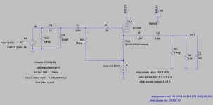
Power supply schematic -
Could someone please verify the heater elevation part. This is my first tube project and I am worried about hum. Will post the pcb also once I am finished with it.
pre schematic:
The three pads near the input are for the pot, plan to use a 50k log pot. I have left the pin 9 floating, gives me the flexibility to try other tubes, 12.6v ones also. I plan to experiment a lot with this circuit. I am going to order a transformer with 110v 200ma secondary and 6.3-0-6.3 2A.
All my designs are named after blues songs, this one will be called Lightning in a bottle.🙂
An externally hosted image should be here but it was not working when we last tested it.
Could someone please verify the heater elevation part. This is my first tube project and I am worried about hum. Will post the pcb also once I am finished with it.
pre schematic:
An externally hosted image should be here but it was not working when we last tested it.
The three pads near the input are for the pot, plan to use a 50k log pot. I have left the pin 9 floating, gives me the flexibility to try other tubes, 12.6v ones also. I plan to experiment a lot with this circuit. I am going to order a transformer with 110v 200ma secondary and 6.3-0-6.3 2A.
All my designs are named after blues songs, this one will be called Lightning in a bottle.🙂
- Status
- Not open for further replies.
- Home
- Amplifiers
- Tubes / Valves
- ecc88 preamp