Hi all,
i'm actually looking for a schematic for an tube preamp or buffer with an ECC82 per channel which will run at roughly 70V (48V rectified and filtered).
I really want to get behind the "witchcraft" of the circuit. So i need some explanations which value is calculated in which way.
Before i get ripped apart for using ether an ECC82 or only 70V:
I want to drive a ss se amplifier with this (that lovely 2sk1058 mosfet amp from Mark Houston) and i got 2 tubes and two transformers already. Even the case is allready there. That's why i'm asking for a schematic which will use only 70V as B+ (if an voltage doubler isn't preferrable).
It must not surpass the High End region. It will be there to glow and to control the volume.
So if someone can give me a hand with this 🙂
Hope you get what i'm talking about in my way of english XD
So, are you running the 12AU7 with a 48V DC supply? Grid current will be a big issue here, do you have a low impedance source to drive this?
A 6922 will run with far less grid current on low voltage than a 12AU7 will. A 6GM8 would be even better.
A 6922 will run with far less grid current on low voltage than a 12AU7 will. A 6GM8 would be even better.
Only problem here is that i don't have any other tubes actually. So the tube will be running at 70VDC.
I saw a video some months ago where an "ordinary" tube preamp runned from 30VDC upwards with nearly no noticable difference.
So this was my intention but i don't know if IT will work and before i break those lovely little Valvo tubes i thought i ask before i build.
I saw a video some months ago where an "ordinary" tube preamp runned from 30VDC upwards with nearly no noticable difference.
So this was my intention but i don't know if IT will work and before i break those lovely little Valvo tubes i thought i ask before i build.
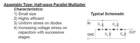
A voltage multiplier is definitely preferable. A 3 stage 1/2 wave parallel setup will yield approx. 200 VDC. A 200 VDC B+ rail is enough for a 12AU7/ECC82 section cathode follower (buffer). The big question is whether or not the 48 VRMS winding has sufficient current capability. If the RMS current capability of that winding is 6X the DC draw of 2X cathode followers, you are good to go.
Do not use the 'U7 triode as a voltage amplifier, as it is non-linear.
BTW, my Deutsch is certainly worse than your English. Ich spreche nür ein klienes bischen Deustch.
Do not use the 'U7 triode as a voltage amplifier, as it is non-linear.
BTW, my Deutsch is certainly worse than your English. Ich spreche nür ein klienes bischen Deustch.
Attachments
The input impedance at the grid of the tube drops dramatically when you do this with a 12AU7. Performance will degrade substantially. How much would it cost you to buy one ECC86 so you can do this properly?I saw a video some months ago where an "ordinary" tube preamp runned from 30VDC upwards with nearly no noticable difference.
Eli's suggestion regarding the voltage multiplier is a good one.
Maybe a little less than 200V also possible? Because i forgot to mention that eben the caps are already here and they are rated 1000uf at 200V... I could go with 4 stages with 470uf rated 450V... But those should be for a tube amp...
So maybe 170V or so... With 3 stages... Possible?
Regarding ECC86... They would run off 70VDC?
@Elli:
That's gutes Deutsch XD
So maybe 170V or so... With 3 stages... Possible?
Regarding ECC86... They would run off 70VDC?
@Elli:
That's gutes Deutsch XD
ECC86 is a low voltage type with a maximum plate voltage of 30V...
https://frank.pocnet.net/sheets/035/6/6GM8.pdf
https://frank.pocnet.net/sheets/035/6/6GM8.pdf
I think there's some confusion here. ECC82 is also called 12AU7, and can run well with a 70v power supply, albeit at low current.
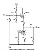
I do not know how much you know about tube operation but I will assume you know that it's a dual triode (you can use one tube for two channels) and it needs 12 volts at 150mA (or 6 volts at 300mA) to power the heater, separately from the 70 volt supply.
Running at1.5mA current,with 45 volts at the plate, you need about 1.5 volts bias, so a resistor of 1000 ohms from cathode to ground will do the job. Bypass that resistor with a low-voltage cap, usually electrolytic, of more than 50 microFarads. From plate to +70v, the plate load resistor would be 15 to 18 kOhms.
I derived these values from the plate curves, as published in the specifications - I used the GE data, but here's the one from Phillips:
https://frank.pocnet.net/sheets/010/e/ECC82.pdf
Last edited:
That it is a dual triode is clear to me. I want to use one tube per channel (looks nicer on the case). I have a transformer cabable of 2x24V and 300mA. So the secondarys pulled together to get 48VAC, put that voltage in a CRCRC filter and get something around 70VDC well filtered.
So far my plan. For the heaters i got an extra transformer cabable of 12VAC and 1,5A. Should be enogh though.
I want to use no input cap but an output cap in the Region of 10uf (those are also laying around in the bin).
Question is how to get the right values for the required resistors...
So far my plan. For the heaters i got an extra transformer cabable of 12VAC and 1,5A. Should be enogh though.
I want to use no input cap but an output cap in the Region of 10uf (those are also laying around in the bin).
Question is how to get the right values for the required resistors...
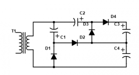
Ok. Since your transformer has enough current, expanding on Elis suggestion of a trippler, I say use a quadrupler.
All caps say 220uF, 160V+, all diodes 600V 2A (for reliability margin). This will give some 240V.
Ad your typical filter after this arrangement (CRC, CLC).
You can then use one tube per channel as included with great results...
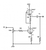
EDIT: If you want gain, use the third attachment, but there's an error. Attach the 1uf cap to the bottom of the 240R not the top.
All caps say 220uF, 160V+, all diodes 600V 2A (for reliability margin). This will give some 240V.
Ad your typical filter after this arrangement (CRC, CLC).
You can then use one tube per channel as included with great results...
EDIT: If you want gain, use the third attachment, but there's an error. Attach the 1uf cap to the bottom of the 240R not the top.
Attachments
Last edited:
So far ok.
I think the vol-pot should get behind the buffer (for lesser distortion)...
The B+ is taken at C3 i think? Or over C3 and C4?
I think the vol-pot should get behind the buffer (for lesser distortion)...
The B+ is taken at C3 i think? Or over C3 and C4?
Over C3 and C4. At C3 you have B+/2.
Yes, you can replace the first 1M in the buffer with 1M pot, 100K pot, whatever vaule you want the input to be... The schematic was from the middle of an amp...
Yes, you can replace the first 1M in the buffer with 1M pot, 100K pot, whatever vaule you want the input to be... The schematic was from the middle of an amp...
As long as sufficient RMS current is available, the number of stages in a 1/2 wave parallel multiplier can be increased "ad infinitum". The WVDC of the cap. in each stage progressively increases, but the losses per stage hold "constant".
Losses cascade when 1/2 wave serial, AKA Cockcroft-Walton, topology is employed. The stresses applied to the diodes and caps. are equal across all stages. However, 1/2 wave serial topology is both inexpensive and cheap (in the grammatically correct sense).
Losses cascade when 1/2 wave serial, AKA Cockcroft-Walton, topology is employed. The stresses applied to the diodes and caps. are equal across all stages. However, 1/2 wave serial topology is both inexpensive and cheap (in the grammatically correct sense).
- Home
- Amplifiers
- Tubes / Valves
- ECC82 with aprox 70V... Instructions needed