Soundwise there's difference in bass reproduction, that's why my concern. It's heavier as a first impression, deeper too. That could reveal an early roll off in the original situation but I'm unsure because I'm listening to radio now, not a habit I must confess. Electrolyte has settled within the last days (it's a conventional PS, quite high impedance) and w.r.t. music reproduction I further can't hear difference between both situations (apart from bass). Tonight I'll establish some feedback to see if bass notes remain the same and dig out the old scope and tonegenerator. And furter I must refresh my theory because no calculation I made was right the first time... I even can't find information on the octave (thought it was an interval ranging from a base to a 10-fold frequency)...
Soundwise there's difference in bass reproduction, that's why my concern. It's heavier as a first impression, deeper too. That could reveal an early roll off in the original situation but I'm unsure because I'm listening to radio now, not a habit I must confess.
In order to calculate the frequency roll off more accurately, you also must consider the output impedance, usually low and mostly neglected, I mean
fo = 1 / [2 π (Rsource+Rload) C]
Input impedance of the following stage will be paralleled with the load, your load actually is low, and when you connect the power amplifier will be lower, and will increase your fo.
Then, the first try would be put a bigger capacitance for C1.
What did you put, 1µF or 4.7µF?
Electrolyte has settled within the last days (it's a conventional PS, quite high impedance) and w.r.t. music reproduction I further can't hear difference between both situations (apart from bass).
As not exists an amplifier better than its power supply, this is a thing you can improve.
And furter I must refresh my theory because no calculation I made was right the first time...
Maybe there are infallible people, that's not my case and I make mistakes all the time; just to give an example, the display size of my old calculator tends to shrink over the years, without new eyeglasses is easier to screw up. 😀
Last edited:
I even can't find information on the octave (thought it was an interval ranging from a base to a 10-fold frequency)...
An octave is twice the base frequency. A decade is ten times the base frequency.
No, the slope is 6 dB / octave
One octave means a 2:1 ratio
I thought that was enough, sorry. 😱
On a side note:
It's called an octave because in the gregorian musical notation system, the one we still use today, the eight whole note (octa = eight, octopus, octagonal, etc.) from the base note is double the frequency.
It's called an octave because in the gregorian musical notation system, the one we still use today, the eight whole note (octa = eight, octopus, octagonal, etc.) from the base note is double the frequency.
On a side note:
It's called an octave because in the gregorian musical notation system, the one we still use today, the eight whole note (octa = eight, octopus, octagonal, etc.) from the base note is double the frequency.
Musical notes expressed in terms of its frequency, at any upper octave goes as 2^n, that's the reason why even order harmonic distortion is the lesser evil.
However, musical notes are seven, i.e.
Do-Re-Mi-Fa-Sol-La-Si
It's called octave the frequency range between two notes that are separated by a 2:1 ratio
Do-Re-Mi-Fa-Sol-La-Si-Do
Yes, you have to count the base note as one, than the next 'do' or 'c' or whatever is the eight, as any musician will tell you.
In order to calculate the frequency roll off more accurately, you also must consider the output impedance...
An externally hosted image should be here but it was not working when we last tested it.
Sorry man but this turns into duck shooting

In the above situation both impedances seem in parallel to me.
That would produce a pole of 1/2π x 3K24 x 10^-6 = 49Hz for a 1uF value for C1.
4,7uF (actual size) gives 1/2π x 3K24 x 4,7 x 10^-6 = 10Hz.
An externally hosted image should be here but it was not working when we last tested it.
2,2uF at 22Hz would be a compromise because of phase shift in the audible region (with better speakers than mine that is).
Soundwise there's difference in bass reproduction, that's why my concern. It's heavier as a first impression, deeper too. That could reveal an early roll off in the original situation but I'm unsure because I'm listening to radio now, not a habit I must confess.
The abnormal bass reproduction belongs to the radio station (3FM, thanks Giel!) I was tuned to for a while. After two CDs of well known recordings the conclusion is that the CDP gives a familiar reproduction. I could hardly distinct the pre from direct connection via the variable output. It seems the pre delivers a clearer sound stage: sharper imaging of instruments and better distinction of the depth of the field. Although the effect is minimal the illusion is there. Intellectually I can't explain why a 'thermal afterburner' would change something for the better, it will probably come down to just the right amount of harmonics, a little IM or channel bleeding I guess.
Is there a sensible test to perform with signal generator and oscilloscope? I could compare square waves for size and form of course but I don't expect anything to show up...
An externally hosted image should be here but it was not working when we last tested it.
This circuit is wrong and won't work.
In the above situation both impedances seem in parallel to me.
That would produce a pole of 1/2π x 3K24 x 10^-6 = 49Hz for a 1uF value for C1.
4,7uF (actual size) gives 1/2π x 3K24 x 4,7 x 10^-6 = 10Hz.
fo = 1 / [2 π (Rsource+Rload) C]
For C1=1µF fo≈10.8 Hz, for C1=4.7µF fo≈2.3 Hz
For C1=1µF fo≈10.8 Hz, for C1=4.7µF fo≈2.3 Hz
Sorry man but this turns into duck shooting
Sorry man, but my intention was only to help you, good luck. 😉
The abnormal bass reproduction belongs to the radio station (3FM, thanks Giel!) I was tuned to for a while. After two CDs of well known recordings the conclusion is that the CDP gives a familiar reproduction. I could hardly distinct the pre from direct connection via the variable output. It seems the pre delivers a clearer sound stage: sharper imaging of instruments and better distinction of the depth of the field. Although the effect is minimal the illusion is there. Intellectually I can't explain why a 'thermal afterburner' would change something for the better, it will probably come down to just the right amount of harmonics, a little IM or channel bleeding I guess.
Is there a sensible test to perform with signal generator and oscilloscope? I could compare square waves for size and form of course but I don't expect anything to show up...
Hey come on, he's trying to break the record for longest continues radio show, so he needs some bass to keep himself awake 😀
But seriously, there's so much processing and compression going on with radio that it's impossible to use it as a reference of any kind.
An externally hosted image should be here but it was not working when we last tested it.
Yajoh, he's makin' it happen.
Never knew there's so much difference between stations.
3FM is compressed and equalised to the limit.
Ok, leak is above the water now.
What's wrong?An externally hosted image should be here but it was not working when we last tested it.
This circuit is wrong and won't work.
fo = 1 / [2 π (Rsource+Rload) C]For C1=1µF fo≈10.8 Hz, for C1=4.7µF fo≈2.3 Hz
In the above situation both impedances seem in parallel to me.
That would produce a pole of 1/2π x 3K24 x 10^-6 = 49Hz for a 1uF value for C1.
4,7uF (actual size) gives 1/2π x 3K24 x 4,7 x 10^-6 = 10Hz.
Johann, I had a quick peek and poke with my scope to obtain some data the empirical way. Remember C1= 4,7uF.
An externally hosted image should be here but it was not working when we last tested it.
2KHz Input=output at 2,0Vrms or 5,7Vpp
An externally hosted image should be here but it was not working when we last tested it.
2KHz Input=2,0Vrms Output=9,7Vrms
An externally hosted image should be here but it was not working when we last tested it.
20KHz Input=2,0Vrms Output=9,6Vrms
An externally hosted image should be here but it was not working when we last tested it.
20HZ Input=2,0Vrms Output=9,5Vrms
An externally hosted image should be here but it was not working when we last tested it.
10HZ Input=2,0Vrms Output=9,1Vrms
So, from 20Hz output voltage is dropping.
At 10Hz it's 0,6Vrms down. 20log(25,7/27,4) = 0,5dB
Seems like the pole is lower than 10Hz, as you predicted.
An externally hosted image should be here but it was not working when we last tested it.An externally hosted image should be here but it was not working when we last tested it.An externally hosted image should be here but it was not working when we last tested it.An externally hosted image should be here but it was not working when we last tested it.
I'm dropping a third of the output voltage here through the devider Zs/Zl.
There's still headroom for some voltage feedback.
Would 5% f.b. be derived from Rfb = 20 Zout ?
Any HF issues to be expected?
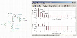
This is an inverting amplifier. I don't think you applied the feedback correctly. Notice all the "grass" in the FFT. This is open loop @ 1.16Vrms output @ 1kHz. Since this is driving 1M ohm, THD is very low. I changed the load to 100k and the open loop THD goes up a lot, as expected, and loop feedback brings it down (when the input level is adjusted to match the open loop output level). The "grass" remains unchanged. So, without loop feedback, and putting the volume control after the gain stage, means that you're basically listening to distortion and noise. If that floats your boat, then so be it, but it's not what audio engineers usually strive for in their designs. There's a very good reason that the volume control goes in the front of the preamp, and that's why it's been done that way for decades now.
Attachments
Last edited:
Well, I can't hear any noise or distortion. Your attempt is appreciated but it's not coherent with reality. Please build it and then give your opinion.
This circuit is wrong and won't work.
What's wrong?

With this circuit you don't need to draw the capacitor, it is implicit into impedance, if you decide to draw it, the load must be put after the capacitor, not before.
Mind you that C1 is connected to cathode of the upper triode, then the load would be a "bridge" for the bottom section of the SRPP.
I guess you actually build your original circuit.
So, from 20Hz output voltage is dropping.
At 10Hz it's 0,6Vrms down. 20log(25,7/27,4) = 0,5dB
Seems like the pole is lower than 10Hz, as you predicted.
Well, at some point I had to hit the nail on the head. 😀
Last edited:
Yes, it's duck shooting for both of us, I was a little upset by that.
Here's the circuit I build:
Of course, you draw a DC circuit and for AC the cap is included.
So, impedance ad up. I'll redo the graphic.
Dirk, would you be so kind to simulate the above circuit.
I didn't get your point for the potmeter at the output.
Baby steps please 😉
Here's the circuit I build:
An externally hosted image should be here but it was not working when we last tested it.
Of course, you draw a DC circuit and for AC the cap is included.
So, impedance ad up. I'll redo the graphic.
Dirk, would you be so kind to simulate the above circuit.
I didn't get your point for the potmeter at the output.
Baby steps please 😉
The "grass", as you call it, is @ -150dB (at least that's what your simulation program wants you to believe). How is this relevant?Notice all the "grass" in the FFT.
I don't think you understand how your circuit works. Connecting the 1Meg load or not won't make much difference. In your schematic, the lower tube sees about (μ+1)*Rk + rp which is about 6K (ECC88). The upper tube acts simply as an active load. You'll need a much lower load in order for SRPP to work as intended (it's called "shunt regulated" for a reason).This is open loop @ 1.16Vrms output @ 1kHz. Since this is driving 1M ohm, THD is very low.
As a side note, closing the feedback loop not only applies the feedback but also lowers the effective load of the circuit significantly (20K at the output) and therefore changing the characteristics.
Last edited:
Good point.As a side note, closing the feedback loop not only applies the feedback but also lowers the effective load of the circuit significantly (20K at the output) and therefore changing the characteristics.
Yes, it's duck shooting for both of us, I was a little upset by that.
Hey, that's unfair, I screwed up with output impedance by 20%, no need to be upset for so little. 🙂
- Status
- Not open for further replies.
- Home
- Member Areas
- The Lounge
- ECC82/12AU7 Line Preamp