Another idea: If you've got yet some ECC40's, but no EBC41, you'd want to completely rearrange the PI section around the triode pair from the original LTP to a voltage amplifier plus a Concertina, see page 4, Fig. B in the yet mentioned Philips ECC40 datsheet. Total voltage gain will be about the same as with a ECC83 LTP, and as EL41's are frugal to drive, a Concertina will work as well. But be aware of it's poor PSRR, i.e. provide good plate supply filtering!
Best regards!
I just saw your reply and thank you for taking your time to answer. Yes I do have a couple (but not 4) EBC41 and I already drilled the holes for the ECC40 and heater wiring 🙄
But definitely a good idea, too late I guess. And yes I know from experience what happens with the Concertina when the B+ is not well filtered, no idea why that happens though.
work in progress
An externally hosted image should be here but it was not working when we last tested it.
There's also this:
http://www.valveheart-bg.com/Scans/pp_i10w.gif
but that phase inverter looks odd, or primitive, with a voltage divider driving the second triode 😕
It's never too late 🙂!
As said before, you can use the same tubes, but you may want to rearrange the PI section around your ECC40.
PSRR of a Concertina is bad due to it's arrangement as a voltage divider (as seen from plate supply), and is even worsened due to the different impedances at the tube's cathode and plate.
Best regards!
There's also this:
http://www.valveheart-bg.com/Scans/pp_i10w.gif
but that phase inverter looks odd, or primitive, with a voltage divider driving the second triode 😕
Given that R9 = R10 = R11 this is quite a good phase inverter - a self balancing paraphase! You could also build that, if you find out the components' values.
Best regards!
Are you really sure about that? The modern (relatively...) 6922/6DJ8/E88CC has nearly five times the gm of the really vintage ECC40.
Best regards!
Best regards!
or this ?
I would go ef40 to channel one , ecc40 channel 2 then use another ecc40 , one section to boost gain and one as cathodyne PI and then another ecc40 to drive each el41.....put your tone stacks after the first ecc40 and ef40....play with the resistors until the volume balance is good between the two channels
Ive done this myself but with 7 pin tubes 6c4 , 6at6, 6aq5 Quad , good results 20+watts cheap too ...
I know this thread is old but this is where people look for ideas....
Last edited:
Hey!
First message in this forum actually. I'm still veeeery new at the moment, and still reading about electronics and learning, but anyway, let me ask a question in this really old thread:
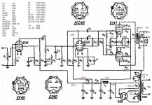
I have used this scheme as a starting point, i've basically done the same preamp stage, but with the ECC40 in cascode ending in a single EL41.
Tried everything, literally everything, but i can't make it sound. Long story short i putted the first stage of the ecc40 in the grid of the second stage and from the plate of the second stage to the grid of the el41. Even if i disconnect completely the second stage of the ecc40 and connect directly the output of the first triode to the el41 i have just a low mushed sound. And it's strange, if i connect the el41 to the ef40 i have more gain than the ecc40.
Yes i tried to swap the tube with a new one, the only concern i have is that i don't have enought negative voltage on the cathode and grid of the ecc40...
Well, let's see if someone will come out with a nice idea, i'm really stuck!
Thanks 😀
First message in this forum actually. I'm still veeeery new at the moment, and still reading about electronics and learning, but anyway, let me ask a question in this really old thread:
Let me propose some mod's and values 🙂 keeps me bizzy 😀
If you don't need the tone control, skip the EF40 and put the volume control on the first grid of the ECC40.
Mona
I have used this scheme as a starting point, i've basically done the same preamp stage, but with the ECC40 in cascode ending in a single EL41.
Tried everything, literally everything, but i can't make it sound. Long story short i putted the first stage of the ecc40 in the grid of the second stage and from the plate of the second stage to the grid of the el41. Even if i disconnect completely the second stage of the ecc40 and connect directly the output of the first triode to the el41 i have just a low mushed sound. And it's strange, if i connect the el41 to the ef40 i have more gain than the ecc40.
Yes i tried to swap the tube with a new one, the only concern i have is that i don't have enought negative voltage on the cathode and grid of the ecc40...
Well, let's see if someone will come out with a nice idea, i'm really stuck!
Thanks 😀
So, your starting point was " this scheme " which is ef40 pentode input, ecc40 phase splitter, push-pull output.
You changed that to ef40 input, ecc40 cascode, single ended output.
Anything you didn't change ?
Besides that " 1st ecc40 connected to grid of 2nd ecc40 " does not describe a cascode .... ?
I am completely lost .... don't expect any useful answer unless you post a schematic drawing of what you actually tried to build.
Last edited:
So, your starting point was " this scheme " which is ef40 pentode input, ecc40 phase splitter, push-pull output.
You changed that to ef40 input, ecc40 cascode, single ended output.
Anything you didn't change ?
Besides that " 1st ecc40 connected to grid of 2nd ecc40 " does not describe a cascode .... ?
I am completely lost .... don't expect any useful answer unless you post a schematic drawing of what you actually tried to build.
You are right, i mispelled the world from cascade to cascode, wich is a really unfortunate mispell.
Anyway, i provide below with the scheme, is the cascade of the ECC40, the exact copy of what i did.

I've measured the voltage on the cathode and it's close to +4v on every triode, and i forgot actually to draw on the scheme the B+ line, but i think you get it.
I hope this will be more helpful 😀
You still don't show what you did with the output stage.
Is it still running in pentode mode or triode ?
Did you adjust the cathode resistor for a single EL41 ?
Did you realize that the original PP output stage had feedback from the transformer to the 1st ECC40 ?
And that the 2nd ECC40 had no gain at all, just providing the inverted signal to the other output tube in PP ?
Did you just leave the FB out ?
Anyway, your cascAding is a major problem.
EF40 into ECC40 into another ECC40 into EL41 in pentode ... that is way too much gain.
The pentode input unbypassed) has gain of 30, the 1st ECC40 (unbypassed) gain of 20, the 3rd ECC40 (bypassed) another gain of 30.
Which gives: 30 x 20 x 30 = 18000 !!!
Anything more than 1mV of input will drive your EL41 into clipping.
And the sheer amount of gain in your setup will most likely cause oscillation, too, both high frequency (causing distortion) and / or low frequency (motor boating).
Last edited:
unless there is something fundamentally wrong with the output stage or the FB , suspect oscillation... i have just a low mushed sound.
another indication that your amp oscillatesAnd it's strange, if i connect the el41 to the ef40 i have more gain than the ecc40.
that could be a quick fix:
take out the ECC40s and connect the EL41 to the EF40 as you already tried;
now connect the feedback resistor 22K from the transformer secondary to the cathode of the ef40;
ground the other end of the secondary;
you should now have the proper gain for line input signals;
(if it doesn't work well, you have to reverse the secondary)
you need feedback anyhow to make pentodes sound;
and use grid stoppers - 1K resistors short and directly soldered to control grid pins.
Last edited:
Hey!You still don't show what you did with the output stage.
Is it still running in pentode mode or triode ?
Did you adjust the cathode resistor for a single EL41 ?
Did you realize that the original PP output stage had feedback from the transformer to the 1st ECC40 ?
And that the 2nd ECC40 had no gain at all, just providing the inverted signal to the other output tube in PP ?
Did you just leave the FB out ?
Anyway, your cascAding is a major problem.
EF40 into ECC40 into another ECC40 into EL41 in pentode ... that is way too much gain.
The pentode input unbypassed) has gain of 30, the 1st ECC40 (unbypassed) gain of 20, the 3rd ECC40 (bypassed) another gain of 30.
Which gives: 30 x 20 x 30 = 18000 !!!
Anything more than 1mV of input will drive your EL41 into clipping.
And the sheer amount of gain in your setup will most likely cause oscillation, too, both high frequency (causing distortion) and / or low frequency (motor boating).
Thanks for the time you took for me, so, the thing is i really don't know a LOT of thing and i'm just messing around with things that i scavange from old radios 🙂.
BTW, maybe i was just clipping the hell out of that EL41, and in fact with one EF40 it's just good, you're definetively right, i'm just an idiot and i haven't took in consideration the fact that the second ECC40 triode was just a phase splitter for the PP. But even if i was connecting only one triode it was the same so... definetively i'm missing something.
And yes, i changed the section of the EL41, and obviously with a different OT.
I've also tried to make 2 EF40 one after another, but i just multiply the noise XD....
I also tried to put grid stoppers, but if i use one EF40 does not make any difference, if i try to put it in the second EF40 (the one i added for experimenting) it make a real difference, but also basically exclude the tone controls.
I will also try to put just the ECC40 alone, skipping the EF40 just for the sake of see what happen.
I've created a benchmark (using an old radio chassis), to test various tubes and experimenting while reading electronics.
Thanks again 😀!!!

OK,
now the EL41 output is triode connected, which means lower gain, lower distortion and lower output power than in pentode,
don't expect more than 1 Watt undistorted with your 250V PS.
Yes, skipping the EF40 and with one ECC40 as input this should work without feedback. Take the one with bypassed cathode resistor.
But believe me, the output EL41 does require grid stoppers, 1K on the grid and 100 ohm on the screen, too.
I always use them and never experienced any negative effects.
On the contrary, I remember my earliest experience with a EL500 which seemed to defy ohms law when triode connected because current and voltage across the cathode resistor did not go together. Until I realized that a DMM one meter away, not connected to anything, showed OL whenever the power to the tube was on. It had turned into a powerful RF transmitter. It required stoppers on both grids to tame that.
The EL41 tube is the same as the EL80 and the pentode system of the ECL86 (6GW8) or PCL86 (14GW8) tube, which has a different heating voltage. All information found is valid for any of the listed tubes I would not agree (through my own experiences!) that the EL41 is prone to thermal "self-destruction" and I believe that some constructors had examples with a bad vacuum, which is why their experiences are bad.

Noooo, i committed a scheme crime. The G2 wasn't connected to the plate but to the beginning of the B+ of the OT.OK,
now the EL41 output is triode connected, which means lower gain, lower distortion and lower output power than in pentode,
don't expect more than 1 Watt undistorted with your 250V PS.
Yes, skipping the EF40 and with one ECC40 as input this should work without feedback. Take the one with bypassed cathode resistor.
But believe me, the output EL41 does require grid stoppers, 1K on the grid and 100 ohm on the screen, too.
I always use them and never experienced any negative effects.
On the contrary, I remember my earliest experience with a EL500 which seemed to defy ohms law when triode connected because current and voltage across the cathode resistor did not go together. Until I realized that a DMM one meter away, not connected to anything, showed OL whenever the power to the tube was on. It had turned into a powerful RF transmitter. It required stoppers on both grids to tame that.
But now that i know that i can do it i will try it 😀!
Today i also experimented a little with the ECC40. Basically with one triode of the ECC40 everything is fine, if i stack up the second triode (in cascade 😆), it start motorboat. I have to learn what happen when it start motorboat like that, is funny because the choke that is held just by a screw start oscillate too 😆, it's just funny to see that, magnetic field that fluctuate so much that it vibrate from the holding leads!
Thanks Sorento (are you also italian?), you really helped me figure out what i was doing wrong 😍!
OT or better off topic, in this forum OT can be misleading XD....
Anyway, now that everything works (more or less) the time of building a single tube amp with a ECL86/PCL86 has finally come!
And today i had the pleasure of breaking an ECC83 on the base, i was assembling an amp and it just disappeared in my hand while i was inserting in the socket. It was just an honest miniwatt that was still working 😢, but i found 2 Miniwatt mC1 and mC3 longplate from a "mistery tubes box" so, it was an exchange in positive.
Thanks to everybody!
- Home
- Amplifiers
- Tubes / Valves
- ECC40 instead of ECC83 rimlock valves build