Wow Lampie do you read the threat (#4)?
@ scholl: your 10 kHz reply has nothing to do with the square wave distortion under discussion.
@ scholl: your 10 kHz reply has nothing to do with the square wave distortion under discussion.
Conclusion: there no general agreement on the cause of that bump.
Damm square wave, wish I never published it, who does it?
Damm square wave, wish I never published it, who does it?
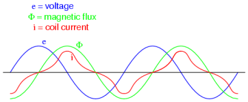
I do, when I want to indicate core saturation.
Check this:
http://www.faqs.org/docs/electric/AC/AC_9.html
Check this:
http://www.faqs.org/docs/electric/AC/AC_9.html
Attachments
In case there is no bump with "normal" program material (like sine waves or music) then no cause for alarm...
Obviously i didn't... sorry about that, i just looked at the wave forms.Wow Lampie do you read the threat (#4)?
Proffessionally you are right, but we diyers sometimes think with their hearts and ears.I guess if you use a 211 tube, u=12, Gm about 3000uMhos, and about 4000 Ohms plate impedance or more at only 55mA quiescent Ip . . .
And then you combine it with a transformer that is not well matched for 211 service, you get what you get.
And, you got it.
Do not increase the B+ voltage; instead, reduce the negative bias voltage until you get 60mA plate current.
(look at the curves at various bias volts and plate volts; check where the slope is curving, not straight. rp is much larger at the curve than at the straight line)
The output transformer is specified at 60mA when set to 11k primary, Right?
I asked you to check that.
Take Lundahl at their word; if it does not meet specs, send it back for a refund ($$$).
Then purchase a less elegant but more capable E-I transformer with a single Air Gap.
I am just thinking out loud.
You have the measured damping factor and 1620 datasheet, why do you not calculate the exact ri of 845 ?
From what I remember it is much lower than you suspect.
A very important factor to troubleshooting the amplifier:
A 20kHz square wave in Post # 12 looks 'textbook perfect' at the input tube, driver tube, AND the output tube Grid.
(There was no negative feedback during that multi trace capture).
The only things left that could cause the odd shaped output from the output transformer secondary are:
The 211 Tube (not likely the cause)
The 211 filament circuit path to ground (not likely the cause)
The non-inductive load resistor on the 8 Ohm tap (not likely the cause) [I hope a good resistor was used, not an open, and not a loudspeaker].
The B+ filtering at the top of the output transformer (not likely the cause)
And, the Only thing left . . . The Output Transformer.
Just my opinions
So . . . how about another 50 Posts to give "fixes" that do not fix that 20kHz square wave shape.
Either Live with the shape; OR Replace the Output transformer; only the original poster can do that.
There is nothing against hearts and ears.
As one trusted reviewer once said: Enjoy the Music
Last edited:
daanve,
You are correct.
My error, 845 tubes not 211 tubes.
Same filament voltage and filament current (10V, 3.25A)
But here are a few important differences:
Approximations:
211 u/2 = 845 u
211 rp/2 = 845 rp
I would say that requires quite different output transformers (but only if you want to have a decent amplifier).
There is No "Plug and Play" here.
It will play alright, but Handel's "Messiah" sounds like the Salvation Army Band.
Just my thoughts.
Last edited:
For an 1.76ohm output resistance I get 1995ohm ri for 845 at 55mA.
Ll1620 tranfo should have worked, well it works, but not optimum.
Ll1620 tranfo should have worked, well it works, but not optimum.
So it is a problem with capacitances. Nothing to do with saturation, class B and other similar stuff because 6 dB fbk will not remove them like this. Moreover, core saturation you would see already at lower frequency where induction would be higher and higher. As I said, from the practical point of view you might not hear anything strange. Unfortunately cannot compare the sound with and without feedback to tell something SPECIFIC about that SQ feature because feedback completely changes the way the amp drives the speakers. This also means that sound might be better without feedback. Try and see what is better for you.

LL1620 datasheet:
Max. primary signal voltage r.m.s. at 30 Hz (all in series) Single End 380V
Secondary output max. about 9.89V RMS at 30Hz.
Max. primary signal voltage r.m.s. at 30 Hz (all in series) Single End 380V
Secondary output max. about 9.89V RMS at 30Hz.
- Home
- Amplifiers
- Tubes / Valves
- EC8010 & AD1 & 845