The most cheap option for me is to keep Lundahls.PSE 801a, custom -very cheap- 5k:8 OPT.
10k SQ
View attachment 1200831
20k SQ
View attachment 1200832
40k SQ
View attachment 1200833
I got an decent 10kHz SQ and an acceptable 26kHz fU.
I am wondering what SQ has the venerable Ongaku that have an fU of 21Khz and uses the most expensive output transformer in the world.
The idea is not to pay for a pair of 845 every year, same with AD1, considering that most of the time I listen to 1W.IMHO 55mA is very low for 845 (yes, I know that this Lundhal OPT primary current is limited, and output power too -13W-), so THD higher than expected.
If you choose another operating point (higher B++, higher anode current), the distortion will decreasing (and power increasing).
The other "bottleneck" is the LF bump (due to the AD1 output impedance, choke impedance, coupling capacitor value).
If it's present, must to increase cathode decoupling.
View attachment 1200836
LF bump does not bother me at all but I will try your suggestion.
Too complicated for me 6A3sUMMERI guess if you use a 211 tube, u=12, Gm about 3000uMhos, and about 4000 Ohms plate impedance or more at only 55mA quiescent Ip . . .
And then you combine it with a transformer that is not well matched for 211 service, you get what you get.
And, you got it.
Do not increase the B+ voltage; instead, reduce the negative bias voltage until you get 60mA plate current.
(look at the curves at various bias volts and plate volts; check where the slope is curving, not straight. rp is much larger at the curve than at the straight line)
The output transformer is specified at 60mA when set to 11k primary, Right?
I asked you to check that.
Take Lundahl at their word; if it does not meet specs, send it back for a refund ($$$).
Then purchase a less elegant but more capable E-I transformer with a single Air Gap.
I am just thinking
If you see the loadline, the desired operating point more than "conservative".The idea is not to pay for a pair of 845 every year, same with AD1, considering that most of the time I listen to 1W.
http://trioda.com/tools/triode.html

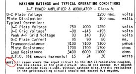
Lower the value of the grid leak resistor of the 845 tube to 18K (or even lower) instead of 180K and increase the value of the coupling cap.
It can be done, why I should not do it?If you see the loadline, the desired operating point more than "conservative".
http://trioda.com/tools/triode.html
View attachment 1200980
Why I would lower the value of 845's grid resistor?
Because you should read the tube datasheets 🙂
Good build, but you could have done it better. Pretty expensive 10 Watts ...
Regards
Attachments

Let the AD1 work a little and choose the resistor value so the distortion of the AD1 will be similar to the 845 to eliminate most at the output....
This will also remove the "bump" seen on the scope.. grid current of the 845 now is determining the load of the R/C circuit and it is lagging...
So the 845 needs to be driven harder... The AD1 can do this easy but is now limited by the poorly chosen values...
This will also remove the "bump" seen on the scope.. grid current of the 845 now is determining the load of the R/C circuit and it is lagging...
So the 845 needs to be driven harder... The AD1 can do this easy but is now limited by the poorly chosen values...
Ups, I was not aware that I am above recommended value.Because you should read the tube datasheets 🙂
Good build, but you could have done it better. Pretty expensive 10 Watts ...
Regards
Love your criticism, only when you do nothing and be nothing, you do not receive criticism.
There is always room for better, so many things to consider like availability of components, mechanical issues, simplicity, doable and not doable...
Don't get me wrong, my comment was only about that you could pick better operating points etc. Simple details that mean a lot! Since you spent already a lot of money. 845 sings better on 1100, 1200V ... like GM-70.Love your criticism, only when you do nothing and be nothing, you do not receive criticism.
I made GM-70 tube monoblocks and I am always experimenting, so, I am not without experience 🙂
Regards
Totally another project to use 1200V for 845.
We diyers we should fell relaxed, if someone throws mud on your project, you do not loose money, nothing to sell.
We diyers we should fell relaxed, if someone throws mud on your project, you do not loose money, nothing to sell.
From the practical point of view it's not a disaster. This is just discussion, maybe next time you will make a different choice....The most cheap option for me is to keep Lundahls.
I got an decent 10kHz SQ and an acceptable 26kHz fU.
I am wondering what SQ has the venerable Ongaku that have an fU of 21Khz and uses the most expensive output transformer in the world.
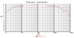
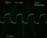
The step shoulder has not direct relationship with frequency response. The lower cut-off only makes the SQ lose its shape but the rise and fall of the SQ can be smooth anyway. I think you have a problem of distributed capacitance. See below an AN transformer with 27KHz -3dB and it's relative 20KHz SQ. It does not have that odd feature. The top and bottom should be horizontally flat but at 20KHz you start to see the effect of the resonance at 40KHz that can be seen in the FR. Of course, if the resonance is better damped it will look better. Optimal source impedance driving the transformer also has a role in it.
Attachments
Last edited:
As said before, it looks like core saturation.Dear Kay, of course it is not crossover distortion.
It is typical, banal, RC low pass filter square wave response. I have at least 3 in this amp( grid stopper resistor and input capacitance on each tube). The added effect can give such square wave response. It is almost perfect response, for my standards, at least.
Best regards!
Your +6 dB peak at 15 Hz of the LC coupling does not help here; after all the output transformer is already "marginal".
Replacing the LC (+ 180k grid resistor) with a 1:1 interstage transformer might improve things quite a lot.
Now you have a chance to listen to one, if you hook yours up to some speakers....Never heard an class B or C amp, how does it sound?
10khz square wave is nard for a SET, this is about as good as it gets.Dear Kay, of course it is not crossover distortion.
It is typical, banal, RC low pass filter square wave response. I have at least 3 in this amp( grid stopper resistor and input capacitance on each tube). The added effect can give such square wave response. It is almost perfect response, for my standards, at least.
Best regards!
Still I am not hearing what you mean.Now you have a chance to listen to one, if you hook yours up to some speakers....
If I want perfect 100khz SQ and 0.001 THD I will listen to my solid state amps, I have many
- Home
- Amplifiers
- Tubes / Valves
- EC8010 & AD1 & 845