The cap is decoupling +V en -V pins of the opamp/HDAM. It also improves performance of LME49710/20.
Hi Nino,
nice mod, hopefully it'll work as you wanted to 😉
Hi keres,
nice, thanks for posting this mod 🙂 I can imagine some nice axial PP cap in there 😉
nice mod, hopefully it'll work as you wanted to 😉
Hi keres,
nice, thanks for posting this mod 🙂 I can imagine some nice axial PP cap in there 😉
+1 !
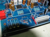
I'm building my 2xAK4399 DAC inside an old Luxman T14 digital tuner. It took me some courage to take out the fine Luxman electronics inside, but I finally did it. I'm going to use it's original LED display, indicator LEDs and switches on the front panel.
Currently I'm programming an Arduino micro controller, to control the DAC and display. User interface is already working fine, soon I'll connect the DAC and test the whole thing. Display is off when DAC is playing normally, to prevent any interference with analog circuit. In fact, the micro controller is in sleep mode most of the time and only wakes up on user input or change of the digital audio input signal. This requires hardware mod also, I'll keep you posted on that.
First picture is of the front panel PCB. 5 LED bar gradually goes to 5 LEDS on when DAC has locked on a valid sp/dif signal. 7 segment LED display shows sampling frequency.
Second picture is the backside of the PCB, with the new LED display driver.
Nice way of recycling uh?
Nice work NinoSimona 🙂 I like that idea. You must post some pics when it is all finished. I am modding my display to turn it off during normal play. Still looking for the right vintage case, there are so many available.
The cap is decoupling +V en -V pins of the opamp/HDAM. It also improves performance of LME49710/20.
Are you implementing a chassis ground? If you are, might it be better to connect the caps between the +ve / -ve pins and ground?
+1 !
I'm building my 2xAK4399 DAC inside an old Luxman T14 digital tuner....Currently I'm programming an Arduino micro controller, to control the DAC and display.
Nice touch, NinoSimona! Have you considered to implement the internal volume control of the AK4399 as well?
Munkyone: I was commenting on keres' post. But you're right, better decouple to ground on both + and - lines, with very short leads preferably. Post your case picture if you find one😉
MBA: Yes I considered, but I have no use for it in my setup. But it's possible to do, maybe an external muting relay is needed There are some adjustments to the controller hardware I made as well, I'll post some more about that later, when I'm in testing phase.
I'm willing to share the code, but my controller isn't a drop in replacement for the current one.
But, on the other hand, if you're skilled in programming C++, it's quite easy to modify or expand my code. it's fun also. The LCD display can also be controlled, it costs you 6 pins, and there's a library with functions already, to get it display whatever you want. I'm using an Arduino Nano, it measures about 2 x 4 cm. and it costs $ 3 - 4 at *bay... If you want to add more hardware, e.g. an OLED display, remote control, or a relay to turn on your table light when your DAC switches to 192k , you may need more I/O pins, you could use an Arduino Mega2560
MBA: Yes I considered, but I have no use for it in my setup. But it's possible to do, maybe an external muting relay is needed There are some adjustments to the controller hardware I made as well, I'll post some more about that later, when I'm in testing phase.
I'm willing to share the code, but my controller isn't a drop in replacement for the current one.
But, on the other hand, if you're skilled in programming C++, it's quite easy to modify or expand my code. it's fun also. The LCD display can also be controlled, it costs you 6 pins, and there's a library with functions already, to get it display whatever you want. I'm using an Arduino Nano, it measures about 2 x 4 cm. and it costs $ 3 - 4 at *bay... If you want to add more hardware, e.g. an OLED display, remote control, or a relay to turn on your table light when your DAC switches to 192k
, you may need more I/O pins, you could use an Arduino Mega2560
Last edited:
Yes I considered, ... I'll post some more about that later, when I'm in testing phase. I'm willing to share the code, but my controller isn't a drop in replacement for the current one...
Exactly - control of the DAC via Arduino platform would be a nice move towards even more flexibility and modifications. Eager to hear more about your work - plese keep us informed!
What do you think about the new modules asynchronous usb?
MisterTao: Leading Taobao Agent - Taobao Product - XMOS U8 daughter card (32BIT 384K)
MisterTao: Leading Taobao Agent - Taobao Product - SA9227 32BIT 384K daughter card
MisterTao: Leading Taobao Agent - Taobao Product - XMOS U8 daughter card (32BIT 384K)
MisterTao: Leading Taobao Agent - Taobao Product - SA9227 32BIT 384K daughter card
phase: Thank you for your comment, I'll keep you posted.
730user: As kukynas says: it depends on what circuit it's for. I have no experience with this particular regulator, output current is very low though.
730user: As kukynas says: it depends on what circuit it's for. I have no experience with this particular regulator, output current is very low though.
Kukynas: Where did you get your Holco resistors and those 390pF caps? I am trying to source as much of the caps and resistors as possible from a single supplier, to save shipping etc.
Thanks.
Thanks.
in your case Farnell France | Composants électroniques | Pièces électroniques ... 😉 otherwise farnell.com
in your case Farnell France | Composants électroniques | Pièces électroniques ... 😉 otherwise farnell.com
Thanks 🙂 Not tried Farnell yet.
TVDD wrong voltage
I'd like to inform you about an issue I discovered with the 2xAK4399 DAC. Wei Liang made a serious mistake by supplying the TVDD pin of the AK4113 receiver IC with the wrong voltage.
The AK4113 (and AK4118 too) is a 3.3V chip, both digital and analog it needs 3.3V power supply. To be able to communicate with 5V chips, it has a special supply pin for the input buffer, TVDD. When the chip is controlled by a 5V MCU (by serial interface and pdn), the TVDD pin must have 5 Volts, not 3.3 Volt, as in this design. All pins are also pulled up to +5V, yet the TVDD is 3.3V. The datasheet is clear about this, it could damage the chip or cause abnormal behavior. I mailed AKM and they confirmed.
I have version 1 PCB, with AK4113. It's quite easy to correct the wrong supply voltage. You need to cut the track leading from TVDD towards the electrolytic capacitor (at the caps end), then solder a wire from it to the +5V track at the bottom. (see picture). Finally you must solder a small 47u electrolytic across the SMT 100n capacitor, to decouple the +5V TVDD pin.
You could say: What does it matter? The DAC works all right!
Ok, at the moment, because I also replaced the AK4113 chip, I can't say if the DAC is performing better now the TVDD is at the right voltage. But because I want to use my own MCU, I wanted to be sure everything is connected the way it should be. I also can't look into the future, whether or not the chip will die eventually due to the wrong voltage. So it's up to you if you want to do the modification or not.
regards
Nino
Attachments
Hi Nino
There is the same error in the 4118 board?
Inviato dal mio LG-D855 utilizzando Tapatalk
There is the same error in the 4118 board?
Inviato dal mio LG-D855 utilizzando Tapatalk
Hi keres
Yes, I think so, at least on the schematic it's not correct. Do you have version2? Maybe you can have a look at your PCB's tracks.
I even wouldn't be surprised when this error was also made in the design of the new (MCU controlled) mono and dual AK4495 DAC. They also use AK4113 / AK4118 as receiver.
Last edited:
Hi keres
Yes, I think so, at least on the schematic it's not correct. Do you have version2? Maybe you can have a look at your PCB's tracks.
I even wouldn't be surprised when this error was also made in the design of the new (MCU controlled) mono and dual AK4495 DAC. They also use AK4113 / AK4118 as receiver.
Thanks NinoSimona. I have just checked the datasheet for the AK4118, which, if I understand it correctly, does specify 2.7v - 5.5v supply at the TVDD pin (13 on AK4118).
I don't fully understand the risks of this pin being at 3.3v instead of 5v. Did AKM give any likely effect in their email reply?
If this is a serious threat to the performance / health of the chip, then perhaps we should let weiliang know.
As for the mod; my board layout is different, so I would need to trace that part of the circuit, to understand where to mod.
Last edited:
The AK4113 (and AK4118 too) is a 3.3V chip, both digital and analog it needs 3.3V power supply. To be able to communicate with 5V chips, it has a special supply pin for the input buffer, TVDD. When the chip is controlled by a 5V MCU (by serial interface and pdn), the TVDD pin must have 5 Volts, not 3.3 Volt, as in this design. All pins are also pulled up to +5V, yet the TVDD is 3.3V. The datasheet is clear about this, it could damage the chip or cause abnormal behavior. I mailed AKM and they confirmed.
Hi Nino,
Thank you for info. At the first page, datasheet says "Operating Voltage: 2.7 to 3.6V with 5V Logic Tolerance" which leads me to think about whatever voltage you supply, "it is 5V tolerance". Quite confusing though.
As I read datasheet, I understand that TVDD's purpose is acting as a buffer so supply voltage of the buffer/TVDD versus logic voltage relation isn't clearly elaborated in datasheet. Can you provide detail about the datasheet section on this subject please?
Regards.
- Status
- Not open for further replies.
- Home
- Source & Line
- Digital Line Level
- ebay:Weiliang Dual X2 AK4399 DAC with LCD