Simple Hobby Circuits For Guitar
We start with some basic volume and tone-control circuits easily implemented, with input and output jacks shown in case separate project-boxes are desired.

Volume controls can be used to make splitters and mixers.

Note that you could, but should not, use a splitter backwards to create a mixer. Rather, rewire the splitter circuit, as shown below, to keep the potentiometers oriented properly. In such cases the correct wiring of a potentiometer has the signal going in at one end of the resistive element with the other end grounded, while the signal is taken out from the wiper. That is how a potentiometer is meant to be used with audio signals. There are cases where the signal goes into the wiper, such as balance controls, but which means the ends of the element are two separate outputs, or where two signals are given at the element ends and their balance is taken from the wiper. But here, we want the element acting as a standard voltage-divider with the wiper providing the output signal.


Next is a simple tone-control with selectable high-end cutoff. Larger capacitor values affect highs more drastically. Comparisons between different switch settings will provide the best understanding of how different caps affect tonality as the Tone pot’s position is changed. This circuit is typical of on-board passive electric-guitar tone-controls except that the rotary switch allows for selecting different bleeder capacitors.

The most common and cheapest capacitors used in guitars are the ceramic disk types. However, they tend to impart a thin sound to the guitar signal. A better capacitor type is the polypropylene film-type capacitor, also called an “orange-drop” capacitor because of its looks. These always sound good and are of high quality, and are more reliable than other capacitor types, but do not cost much more than ceramic-disk types. The most expensive capacitors are the paper-in-oil electrolytic capacitors, and if you want vintage sound, especially if your guitar has humbucker pickups, these are often chosen for that purpose. There are even NOS paper-in-oil capacitors available online, but which often command extreme prices. Therefore, for the most bang or the buck, use polypropylene orange-drops instead. Electronics parts are available at www.stewmac.com , and metal project-boxes at www.parts-express.com . Other electronics sources include www.mouser.com, www.digikey.com, and www.newark.com.
For any project in this post, or effect or effects-line, here is a bypass circuit, if such a circuit is desired.

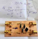
If you get an annoying 60 Hz line buzz from your guitar or effects device, the notch filter below will cut it out. This is called a “Twin-T” notch filter and cuts the frequency to be notched by -12 dB. The formula for part values is provided in case some other notched frequency is to be addressed with the same kind of circuit. I do not recommend using potentiometers to make this a variable notch filter, accepting experimentation.

The wah pedal involves a circuit where a single potentiometer sets the frequency of a notch filter, but the adjustable wah effect cannot be implemented passively. All wah-pedal circuits involve active circuitry using either transistors or op-amps, or both. Note, however, that wah-pedal circuits are easily looked up by searching the phrase "wah pedal circuits", or similar.
We start with some basic volume and tone-control circuits easily implemented, with input and output jacks shown in case separate project-boxes are desired.
Volume controls can be used to make splitters and mixers.
Note that you could, but should not, use a splitter backwards to create a mixer. Rather, rewire the splitter circuit, as shown below, to keep the potentiometers oriented properly. In such cases the correct wiring of a potentiometer has the signal going in at one end of the resistive element with the other end grounded, while the signal is taken out from the wiper. That is how a potentiometer is meant to be used with audio signals. There are cases where the signal goes into the wiper, such as balance controls, but which means the ends of the element are two separate outputs, or where two signals are given at the element ends and their balance is taken from the wiper. But here, we want the element acting as a standard voltage-divider with the wiper providing the output signal.
Next is a simple tone-control with selectable high-end cutoff. Larger capacitor values affect highs more drastically. Comparisons between different switch settings will provide the best understanding of how different caps affect tonality as the Tone pot’s position is changed. This circuit is typical of on-board passive electric-guitar tone-controls except that the rotary switch allows for selecting different bleeder capacitors.
The most common and cheapest capacitors used in guitars are the ceramic disk types. However, they tend to impart a thin sound to the guitar signal. A better capacitor type is the polypropylene film-type capacitor, also called an “orange-drop” capacitor because of its looks. These always sound good and are of high quality, and are more reliable than other capacitor types, but do not cost much more than ceramic-disk types. The most expensive capacitors are the paper-in-oil electrolytic capacitors, and if you want vintage sound, especially if your guitar has humbucker pickups, these are often chosen for that purpose. There are even NOS paper-in-oil capacitors available online, but which often command extreme prices. Therefore, for the most bang or the buck, use polypropylene orange-drops instead. Electronics parts are available at www.stewmac.com , and metal project-boxes at www.parts-express.com . Other electronics sources include www.mouser.com, www.digikey.com, and www.newark.com.
For any project in this post, or effect or effects-line, here is a bypass circuit, if such a circuit is desired.
If you get an annoying 60 Hz line buzz from your guitar or effects device, the notch filter below will cut it out. This is called a “Twin-T” notch filter and cuts the frequency to be notched by -12 dB. The formula for part values is provided in case some other notched frequency is to be addressed with the same kind of circuit. I do not recommend using potentiometers to make this a variable notch filter, accepting experimentation.
The wah pedal involves a circuit where a single potentiometer sets the frequency of a notch filter, but the adjustable wah effect cannot be implemented passively. All wah-pedal circuits involve active circuitry using either transistors or op-amps, or both. Note, however, that wah-pedal circuits are easily looked up by searching the phrase "wah pedal circuits", or similar.

What follows are two of the most common tone-control circuits used in guitar-amps and effects. The first is a 2-band “Passive Baxandall” type of tone control, and the second is a 3-band “Fender Tone-Stack”. Either type works great before or after any stomp-box.


Continuing the topic of tone-control circuits, we can consider basic passive filters using resistors and capacitors but no coils. A simple high-pass filter has a capacitor in the signal path but a resistor to ground, while a low-pass filter has just the opposite, as shown below. The formula for the corner frequency is the same for either filter, whether it is a high corner or low corner frequency. The formula is f = 1 / [(6.283)RC] where f is the corner frequency, R is the resistor value in ohms, and C is the capacitor value in farads (F). However, resistor values are typically large (e.g., kilohms) while capacitor values are always small (e.g., microfarads). It is assumed here that readers are already familiar with how to handle such part-values using a calculator.

With the low-pass filter, there is a resistor in the signal path so it is best to use a fairly low value to keep from attenuating the signal too much. But with a high-pass filter, the resistor is actually a shunt to ground and should thus be as large as practical. Since both filters use the same formula for capacitor and resistor values, the very same values will work for either filter, where the low-pass filter passes frequencies above the desired corner frequencies while the high-pass filter passes frequencies above it.
Here is a table of example values. Note, however, that it is best to use indicated values where R < 10k for the low-pass filter but R > 1k for the high-pass filter. The very same corner frequency works for either filter -- just interchange the placement of R and C to change from high-pass to low-pass or vice-versa.
RC Filter Formulas: f = 1 / [ (6.283)RC ] or C = 1 / [ (6.283)Rf ] ,
where f is frequency in Hertz, R is resistance in ohms, and C is capacitance in Farads.

Note: I did not determine all the above values using the formula myself but employed an online RC filter calculator that used the same formula.
Of course, you can put a low-pass in series with a high-pass to make a bandpass filter, where the low-pass corner is higher than the high-pass corner.

Note though that the filter only offers -3dB per octave of attenuation (slope) beyond a given corner frequency. So, for a -6dB slope, use two filters in series. However, don’t use more than two filters of any kind in series (low-pass, high-pass, or bandpass) since a slope that is too steep will make the filter sound like a frequency switch rather than a filter.
Apply a low-pass filter with a high corner to cut brittleness from a trebly guitar or effects device, or use a high-pass filter with a low corner to cut lows that are too boomy. Or use a band-pass filter to limit unwanted frequencies outside a desired range.
Alternatively, use passive filters to make line-level passive crossovers. Below we give 2-way and 3-way crossovers for the guitar. Use the 2-way for splitting the guitar signal to send it to two amplifiers or effects where one is for handling high frequencies while the other is for the lows. Or use the 3-way to split the guitar signal into three frequency ranges; highs, mids, and lows.
The first set of drawings does not provide a means of limiting extreme highs or lows, as most amplifiers and effects have built-in frequency-limiting circuitry. However, if upper and lower limits different from the standard 20 kHz high and 20 Hz low are desired, the high-pass and low-pass filters of a crossover can be changed to bandpass filters simply by adding a low-pass filter with a high corner in series to the high-pass filter, and a high-pass filter with a low corner in series with the low-pass filter. For example, there is little need to go above about 17 or 18 kHz, or below 30 Hz, for most audio work. However, with either kind of crossover topology, make sure to overlap the lows of the high-pass and highs of the low-pass within an octave of each middle bandpass filter limit.

Do not use these crossovers between speaker and amplifier. “Line-level” means low-level signals, from passive guitar output (a few hundred millivolts) up to 1 volt peak-to-peak from active guitar outputs or effects device outputs.

The guitar’s natural notes, on a 24-fret guitar, go from 82 Hz to 1.32 kHz. Usually, it is unnecessary to go below about 80 Hz for the lows, or the guitar can get too bassy, while it is unnecessary to go higher than about three octaves above the highest note, which means around 10 kHz. Highs above 10 kHz don’t sound like tones but are more like symbol sizzle and high-end hissing noise. In fact, the recommended EQ range for the 6-string electric guitar is generally from 80 Hz to about 8 kHz, including allowing for effects such as distortion overtones and/or higher-octave stomp-boxes.
The crossovers above are based on 700 Hz being the middle frequency in the guitar’s range, but allow for overlaps, so there will be no missing frequencies in either the 2-way or 3-way crossovers, while higher and lower frequency extremes are not limited since the built-in frequency limits of effects and amps already take the extremes into account.
Also, adding volume controls will help to set the frequency-bands at equal signal levels.

But while you’re at it, you can use bandpass filters with separate volume controls to make a 5-band equalizer, which provides a great deal of tonal control.

Frequency centers are; 14 kHz, 5.3 kHz, 1.6 kHz, 520 Hz, and 132 Hz.
For best results, put this circuit just before the amplifier, so it will allow for tailoring the overall sound of a guitar used with two or more effects devices. Most guitars only have a basic tone-control onboard, and most stomp-box effects only have bass and treble controls, at best. And even when a processor is used, they normally only provide three bands of tone control. Hence, the above circuit lets the user dial in just the right blend of frequencies according to personal preference. Of course, pair this circuit with the bypass circuit given earlier to use it selectively.
Continuing the topic of tone-control circuits, we can consider basic passive filters using resistors and capacitors but no coils. A simple high-pass filter has a capacitor in the signal path but a resistor to ground, while a low-pass filter has just the opposite, as shown below. The formula for the corner frequency is the same for either filter, whether it is a high corner or low corner frequency. The formula is f = 1 / [(6.283)RC] where f is the corner frequency, R is the resistor value in ohms, and C is the capacitor value in farads (F). However, resistor values are typically large (e.g., kilohms) while capacitor values are always small (e.g., microfarads). It is assumed here that readers are already familiar with how to handle such part-values using a calculator.
With the low-pass filter, there is a resistor in the signal path so it is best to use a fairly low value to keep from attenuating the signal too much. But with a high-pass filter, the resistor is actually a shunt to ground and should thus be as large as practical. Since both filters use the same formula for capacitor and resistor values, the very same values will work for either filter, where the low-pass filter passes frequencies above the desired corner frequencies while the high-pass filter passes frequencies above it.
Here is a table of example values. Note, however, that it is best to use indicated values where R < 10k for the low-pass filter but R > 1k for the high-pass filter. The very same corner frequency works for either filter -- just interchange the placement of R and C to change from high-pass to low-pass or vice-versa.
RC Filter Formulas: f = 1 / [ (6.283)RC ] or C = 1 / [ (6.283)Rf ] ,
where f is frequency in Hertz, R is resistance in ohms, and C is capacitance in Farads.
Note: I did not determine all the above values using the formula myself but employed an online RC filter calculator that used the same formula.
Of course, you can put a low-pass in series with a high-pass to make a bandpass filter, where the low-pass corner is higher than the high-pass corner.
Note though that the filter only offers -3dB per octave of attenuation (slope) beyond a given corner frequency. So, for a -6dB slope, use two filters in series. However, don’t use more than two filters of any kind in series (low-pass, high-pass, or bandpass) since a slope that is too steep will make the filter sound like a frequency switch rather than a filter.
Apply a low-pass filter with a high corner to cut brittleness from a trebly guitar or effects device, or use a high-pass filter with a low corner to cut lows that are too boomy. Or use a band-pass filter to limit unwanted frequencies outside a desired range.
Alternatively, use passive filters to make line-level passive crossovers. Below we give 2-way and 3-way crossovers for the guitar. Use the 2-way for splitting the guitar signal to send it to two amplifiers or effects where one is for handling high frequencies while the other is for the lows. Or use the 3-way to split the guitar signal into three frequency ranges; highs, mids, and lows.
The first set of drawings does not provide a means of limiting extreme highs or lows, as most amplifiers and effects have built-in frequency-limiting circuitry. However, if upper and lower limits different from the standard 20 kHz high and 20 Hz low are desired, the high-pass and low-pass filters of a crossover can be changed to bandpass filters simply by adding a low-pass filter with a high corner in series to the high-pass filter, and a high-pass filter with a low corner in series with the low-pass filter. For example, there is little need to go above about 17 or 18 kHz, or below 30 Hz, for most audio work. However, with either kind of crossover topology, make sure to overlap the lows of the high-pass and highs of the low-pass within an octave of each middle bandpass filter limit.
Do not use these crossovers between speaker and amplifier. “Line-level” means low-level signals, from passive guitar output (a few hundred millivolts) up to 1 volt peak-to-peak from active guitar outputs or effects device outputs.
The guitar’s natural notes, on a 24-fret guitar, go from 82 Hz to 1.32 kHz. Usually, it is unnecessary to go below about 80 Hz for the lows, or the guitar can get too bassy, while it is unnecessary to go higher than about three octaves above the highest note, which means around 10 kHz. Highs above 10 kHz don’t sound like tones but are more like symbol sizzle and high-end hissing noise. In fact, the recommended EQ range for the 6-string electric guitar is generally from 80 Hz to about 8 kHz, including allowing for effects such as distortion overtones and/or higher-octave stomp-boxes.
The crossovers above are based on 700 Hz being the middle frequency in the guitar’s range, but allow for overlaps, so there will be no missing frequencies in either the 2-way or 3-way crossovers, while higher and lower frequency extremes are not limited since the built-in frequency limits of effects and amps already take the extremes into account.
Also, adding volume controls will help to set the frequency-bands at equal signal levels.
But while you’re at it, you can use bandpass filters with separate volume controls to make a 5-band equalizer, which provides a great deal of tonal control.
Frequency centers are; 14 kHz, 5.3 kHz, 1.6 kHz, 520 Hz, and 132 Hz.
For best results, put this circuit just before the amplifier, so it will allow for tailoring the overall sound of a guitar used with two or more effects devices. Most guitars only have a basic tone-control onboard, and most stomp-box effects only have bass and treble controls, at best. And even when a processor is used, they normally only provide three bands of tone control. Hence, the above circuit lets the user dial in just the right blend of frequencies according to personal preference. Of course, pair this circuit with the bypass circuit given earlier to use it selectively.
Note that diodes provide clipping, instead of overdriving tubes, transistors, or op-amps. The principle is fairly simple. In the old days, the way to get distortion was to overdrive the tubes in an amp or the transistors in an amp or an effect. Later on, after op-amps became common, overdriving an op-amp would do the same thing, and certain types (JFETs) sounded better than others. The distortion was the result of an overdriven device chopping-off the tops and the bottoms of the signal, called “clipping”, because overdriving such devices makes them attempt to exceed design parameters. Doing so without going too far with an input signal allows clipping without destroying the device (tube, transistor, or op-amp). Thus was born the practice among many guitarists of using distortion to enhance solos and to get heavy and/or chunky rhythms, and so came the proliferation of stomp-box fuzz effects, overdrive boosters, and distortion units, and also the preference for tube-amps offering desirable overdriven tone. However, it was also discovered that diodes can be used to cause clipping without the need to overdrive electronic devices, but which also result in pleasing fuzz tones.
The following circuit is an example of how diodes can be used to impart distortion to any guitar signal. It is based on a project called the “Mod Box” that appeared in the May ’97 issue of Electronics Now magazine. And while that article is dated, the circuitry remains valid. The diagram below is based on the distortion subcircuit of the article’s circuit but requires a high-gain stomp-box of some kind between it’s input and the guitar.

The circuit below does not include a volume or tone control, but can still be used, as shown, between the guitar and a stomp-box providing gain, since the guitar and most effects have at least one tone-control and one volume-control of their own. Otherwise, use one of the volume or tone-control circuits given earlier at this circuit’s output.

The nature of the distortion caused by the different types of diodes is due to the material of the diodes. Silicone diodes give harsher sound than germanium diodes, while LEDs produce brighter sounds than either, but which is said to be better than sounds given by silicone diodes. Also, the symmetry of the diode arrangements makes a difference in the distortion produced, hence the symmetry switches, which allow the user to select different settings. Hint: Having one diode on one side of a group but two on the other side is said to emphasize even-order harmonics in the fuzz sound.

Additional Notes: Switching-out all the diodes in a group will not cause the signal to drop out, but will likely boost it, since the diodes each attenuate the signal a bit, so using all four diodes in a group attenuates the signal the most significantly; hence the need for a high-gain device between the guitar and any one of these circuits' inputs. The outputs, however, can go to any active or passive circuit, including other stomp-boxes or directly to an amplifier.
EOF
The following circuit is an example of how diodes can be used to impart distortion to any guitar signal. It is based on a project called the “Mod Box” that appeared in the May ’97 issue of Electronics Now magazine. And while that article is dated, the circuitry remains valid. The diagram below is based on the distortion subcircuit of the article’s circuit but requires a high-gain stomp-box of some kind between it’s input and the guitar.
The circuit below does not include a volume or tone control, but can still be used, as shown, between the guitar and a stomp-box providing gain, since the guitar and most effects have at least one tone-control and one volume-control of their own. Otherwise, use one of the volume or tone-control circuits given earlier at this circuit’s output.
The nature of the distortion caused by the different types of diodes is due to the material of the diodes. Silicone diodes give harsher sound than germanium diodes, while LEDs produce brighter sounds than either, but which is said to be better than sounds given by silicone diodes. Also, the symmetry of the diode arrangements makes a difference in the distortion produced, hence the symmetry switches, which allow the user to select different settings. Hint: Having one diode on one side of a group but two on the other side is said to emphasize even-order harmonics in the fuzz sound.
Additional Notes: Switching-out all the diodes in a group will not cause the signal to drop out, but will likely boost it, since the diodes each attenuate the signal a bit, so using all four diodes in a group attenuates the signal the most significantly; hence the need for a high-gain device between the guitar and any one of these circuits' inputs. The outputs, however, can go to any active or passive circuit, including other stomp-boxes or directly to an amplifier.
EOF
To keep external DC out of the pots and switches.
Of course, the capacitors should be bipolar types, since we don't know which polarity it will be.
Of course, the capacitors should be bipolar types, since we don't know which polarity it will be.
Nice passive circuits.
I will experiment with some. Looking to make some passive eq before headphone amp. Simple, just extreme highs and some lows. Nothing in the middle.
I dislike baxandall tone control because it starts in the middle. If your headphones neels just a help below 30Hz, adding baxandall creates midbass hump. Same applies for bookshelf.
Similarly if only correction needed in highs is above 10kHz, baxandall will create nasty shout around 2-3kHz.
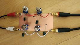
Will experiment with cap values in circuit like this...
I will experiment with some. Looking to make some passive eq before headphone amp. Simple, just extreme highs and some lows. Nothing in the middle.
I dislike baxandall tone control because it starts in the middle. If your headphones neels just a help below 30Hz, adding baxandall creates midbass hump. Same applies for bookshelf.
Similarly if only correction needed in highs is above 10kHz, baxandall will create nasty shout around 2-3kHz.
Will experiment with cap values in circuit like this...
Attachments
It would be good if you also can say something about using these circuits in actual equipment.
Are there requirements for the impedance of the driving source?
How much load can these circuits handle and still work as advertised? Do they need to be buffered?
Jan
Are there requirements for the impedance of the driving source?
How much load can these circuits handle and still work as advertised? Do they need to be buffered?
Jan
Although most are intended as guitar circuits, I intend to use passive circuits between signal source (mp3 or cd player) and headphone amp.
Hello Kurtus,
About the "2 to 1 Mixer" and the "2 to 1 Mixer with Separate Tone Controls" in your first post:
I think that the volume controls will influence each other quite a lot. In the most extreme case, namely when the volume of one of the channels is set at zero, the other channel gets shorted to ground, so there will be no output.
To prevent this, two resistors have to be added between each wiper and the 10K resistor at the output. Since these mixers are supposed to work at guitar levels, the value of the two extra resistors has to be high (470K or even higher to ensure that the input impedance does not get too low when one volume control is set to zero). This will however cause quit insertion loss.
About the "Passive 5-band EQ" in your second post:
I think that the tone controls of the 5 bands will influence each other quite a lot. In the most extreme case, namely when the wiper of one of the bands is set at the down position, the other 4 bands get shorted to ground, so there will be no output.
Again resistors (now five in total) between each wiper and the 10K resistor will prevent this. But again, this will cause insertion loss.
Last edited:
Good points all around, but I posted what I posted and I'm not changing things this time around.
Consider these all to be experimental circuits, and do with them what you will.
Also, readers can consider your comments and decide if they want to make changes before building a given circuit, then test and experiment accordingly.
Thanks.
Consider these all to be experimental circuits, and do with them what you will.
Also, readers can consider your comments and decide if they want to make changes before building a given circuit, then test and experiment accordingly.
Thanks.
That's disappointing. I'd be interested, but without knowing the allowed load and source requirements, it's a gamble.
Where did you find these circuits, maybe I can look it up myself.
Jan
Where did you find these circuits, maybe I can look it up myself.
Jan
No need for disappointment. Observe that these are passive circuits. There are no load or source requirements. And they are all experimental, so a builder must determine such requirements by taking actual measurements when active devices are used on the input and/or output, but where the requirements will be for the active devices themselves, not the stand-alone passive circuitry. Such requirements could be stated but would involve ranges of parameters, not specifics without active devices driving a given passive circuit or amplifying or otherwise processing the output, and I have not done that.
Also, because they are passive, the given circuits only offer attenuation, no boosting, of either the signal-level or certain frequencies, or both. My intent was to offer experimental passive circuits for people to look into, to build and test if desired. Furthermore, a previous comment mentioned that circuits with multiple outputs will involve interactions between the different outputs when a potentiometer of one channel is changed, which is true enough. Testing of a built circuit will determine how extreme such interactions may be, though that should not be prohibitive in any case. On the other hand, it would be easy enough to use op-amps to provide separation between such channels, even mere unity-gain buffers (voltage followers); one for each channel. But this thread was meant for looking at passive circuits of general interest to hobbyists. Yet, it's good to point out flaws and potential problems should anyone actually desire to build some of these circuits. It is wise to work things out "on-paper" before committing to an actual build project.
One flaw I noticed myself, but have not corrected, is that the output volume pot on the Distortion Matrix is oriented incorrectly, according to the standard wiring method of volume pots. The output signal should instead be going into the top of the element and the signal taken from the wiper. The way it is shown, there will be a feedback loop created by the pot, though that may not be such a bad thing if distortion is what you are after. However, should someone build this circuit, you may want to rewire the output pot there so that the output signal is taken from the wiper, not fed into it.
The question was also asked as to the reason for polarized capacitors on the distortion circuits. Originally, they were intended to be paper-in-oil types, to get a vintage sound from the circuit. However, such caps, especially NOS units, are now too costly, and the circuits are not worth that kind of investment. Rather, it is perfectly reasonable to use other caps instead, such as nonpol;orized aluminum electrolytics or film-type polypropylene (orange-drops), depending on personal preference. A convenient source for either is www.parts-express.com .
I intend soon to begin posting active circuits utilizing some of the passive circuits I have given for this thread, starting with single-battery guitar preamps suitable for stomp-box applications. Look for them under this the same "Electronic Design" heading.
Passive circuitry can increase either voltage or current, just not power (their product).
Like in a transformer, for example.
Like in a transformer, for example.
But of course there are load and source requirements. Or should be.There are no load or source requirements.
Source and load impedances, if not ideal (zero source and infinite load), will disrupt something. For example, volume control in the first picture will not exhibit log characteristic in spite of using log potentiometer, if loaded with 47k input impedance of the next stage.
Otherwise, you made good introduction to passive circuits.
Sonce,
I stand by my comments in Post #12, but your points are well taken.
A better volume-control has a fixed resistor from wiper to ground on the order of 1/10 the pot element's resistance, which will make a log pot work properly; i.e., what is called an "audio-taper" potentiometer. A beginner doing research on these circuits should encounter that fact sooner or later. But if a beginner is not doing their own research, then they are making a big mistake taking for granted the correctness of any diagrams they find online,
Thanks for your reply.
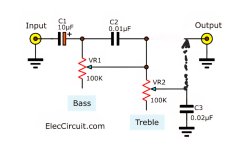
Well, i did the circuit i posted and its total bust. The way its drawn treble does not even work, the output has to come from the wiper of second pot. Plus both controls work only in the negative, so not for me.Nice passive circuits.
I will experiment with some. Looking to make some passive eq before headphone amp. Simple, just extreme highs and some lows. Nothing in the middle.
I dislike baxandall tone control because it starts in the middle. If your headphones neels just a help below 30Hz, adding baxandall creates midbass hump. Same applies for bookshelf.
Similarly if only correction needed in highs is above 10kHz, baxandall will create nasty shout around 2-3kHz.
Will experiment with cap values in circuit like this...
I will likely experiment with passive loudness circuits next.
Attachments
Last edited:
I dislike baxandall tone control because it starts in the middle. If your headphones neels just a help below 30Hz, adding baxandall creates midbass hump. Same applies for bookshelf.
Similarly if only correction needed in highs is above 10kHz, baxandall will create nasty shout around 2-3kHz.
Will experiment with cap values in circuit like this...
You might like the Viddeleer tone control. It's an active tone control that was published in the late 1940's and 1950's by L. V. Viddeleer, so it is roughly as old as the Baxandall tone control.
At first sight, it looks like the dual of the Baxandall tone control: Baxandall uses shunt feedback with resistors and capacitors, while Viddeleer uses series feedback, resistors and an inductor, at least for the bass control (the inductor in the treble control is only meant to limit the amount of ultrasonic treble boost). The way the tone control works at not too extreme settings is very different, though. It mostly affects the extreme frequencies when the setting is close to the centre. Unfortunately, it never got popular.
Last edited:
To Adason,
You did not specify the circuit you tried. Sorry it did not work out. But these circuits are for high-Z guitar signals, not headphones.
Anyway, I am posting more volume and tone controls. The 2-band control you noted is among them (labeled "2-Band Tone-Control 2 w. Volume").
You did not specify the circuit you tried. Sorry it did not work out. But these circuits are for high-Z guitar signals, not headphones.
Anyway, I am posting more volume and tone controls. The 2-band control you noted is among them (labeled "2-Band Tone-Control 2 w. Volume").
Last edited:
More Passive Hobby Circuits for Guitar
Here are additional volume and tone controls, with most found online. My sources are given at the end of this post. Each diagram is labeled uniquely, includes all part-values, are from reliable sources, and some include extra application information.

The Treble Compensation circuit at left below helps to keep the highs from falling off when the volume control is turned down. Volume pots act like low-pass filters, thus cut highs when turned down. The circuit below keeps the highs from being cut too much.
The Attenuator shown at right below is an L-type for which part-values were obtained from an old Allied Electronics Data Handbook. However, the same or other values can be obtained using an online calculator linked here. https://www.k7mem.com/Res_Attenuator.html

The tone-control circuits shown next were obtained using an online search.


The Fender-Style Tone-Stack below was originally obtained from a Bassman schematic, though the same circuit can also be found online at the calculator website I site at the end of this post, along with other tone-control circuits from many well-known amplifiers.

The “Generic” tone-controls below are derived from circuits in my print collection. But I have confirmed that similar circuits exist online and can easily be found by searching the phrase “Passive Tone Control Circuit Diagrams”. The main difference is that I have added the Treble-Compensated Volume control.


Remember that these are all experimental circuits. No claim can be made that any of them will work as desired should someone decide to build one, in which case I advise obtaining parts and making test-circuits on breadboards before committing to a soldered build project. Also, each soldered built circuit must be in a grounded metal enclosure.
My Sources:
(1) General internet searches using the Bing search-engine. Example Result: Better Volume Control.
(2) “Yet Another Tone Stack Calculator” by Yuri Turov (with Duncan Amps). This is a very useful site. I highly recommend it.
Here’s the link: https://tonestack.yuriturov.com
(3) “Elliott Sound Products” site. A treasure-trove of useful schematic diagrams and hobby circuits of all kinds. Here’s that link: https://www.sound-au.com
(4) Various print sources I have collected over the years, including various electronics magazines and technical manuals, numerous loose pages and page photocopies from such sources, and a number of SAMS Photofact folders.
EOF
Here are additional volume and tone controls, with most found online. My sources are given at the end of this post. Each diagram is labeled uniquely, includes all part-values, are from reliable sources, and some include extra application information.
The Treble Compensation circuit at left below helps to keep the highs from falling off when the volume control is turned down. Volume pots act like low-pass filters, thus cut highs when turned down. The circuit below keeps the highs from being cut too much.
The Attenuator shown at right below is an L-type for which part-values were obtained from an old Allied Electronics Data Handbook. However, the same or other values can be obtained using an online calculator linked here. https://www.k7mem.com/Res_Attenuator.html
The tone-control circuits shown next were obtained using an online search.
The Fender-Style Tone-Stack below was originally obtained from a Bassman schematic, though the same circuit can also be found online at the calculator website I site at the end of this post, along with other tone-control circuits from many well-known amplifiers.
The “Generic” tone-controls below are derived from circuits in my print collection. But I have confirmed that similar circuits exist online and can easily be found by searching the phrase “Passive Tone Control Circuit Diagrams”. The main difference is that I have added the Treble-Compensated Volume control.
Remember that these are all experimental circuits. No claim can be made that any of them will work as desired should someone decide to build one, in which case I advise obtaining parts and making test-circuits on breadboards before committing to a soldered build project. Also, each soldered built circuit must be in a grounded metal enclosure.
My Sources:
(1) General internet searches using the Bing search-engine. Example Result: Better Volume Control.
(2) “Yet Another Tone Stack Calculator” by Yuri Turov (with Duncan Amps). This is a very useful site. I highly recommend it.
Here’s the link: https://tonestack.yuriturov.com
(3) “Elliott Sound Products” site. A treasure-trove of useful schematic diagrams and hobby circuits of all kinds. Here’s that link: https://www.sound-au.com
(4) Various print sources I have collected over the years, including various electronics magazines and technical manuals, numerous loose pages and page photocopies from such sources, and a number of SAMS Photofact folders.
EOF
- Home
- Design & Build
- Electronic Design
- Easy Passive Circuits