An NTC for current limiting goes in series with the mains input - between fuse/switch and PT primary is preferred. I put a sleeve of heatshrink tube over the NTC - to confine debris if it fails for some reason - similar to putting heatshrink over a MOV for same reason. If your measurement of 1.2 ohm for PT primary is within an ohm of being accurate (did you measure the resistance with probes shorted?) then you may be able to appreciate the significant benefit of what a cold resistance of 10 ohm will do in suppressing initial turn-on current peak levels (and hence to the stress on the relay contacts if they bounce).
I think for what you are doing a solid state relay would work better that a mechanical relay.
Zero voltage switching is the best approach but I have no idea how one could implement this with a relay. There's too much delay in energizing the relay coil. Solid state relays are available with zero crossing triggering built in. A snubber will reduce the effect but acts on voltage transients.Your problem is with inrush current. Soft turn on using a power resistor works well but is cumbersome. An MOV is more likely a better solution but again acts on voltage transients.
Zero voltage switching is the best approach but I have no idea how one could implement this with a relay. There's too much delay in energizing the relay coil. Solid state relays are available with zero crossing triggering built in. A snubber will reduce the effect but acts on voltage transients.Your problem is with inrush current. Soft turn on using a power resistor works well but is cumbersome. An MOV is more likely a better solution but again acts on voltage transients.
SSR's have specs that may need the PT inrush current level below the 1 second repetitive type spec. Your PT may have peak current levels at turn on that are well above say 10x3 = 30A, and may exceed say 100A, so an SSR with something like 50A continuous rating may be required. There is some leakage through an SSR.
Putting an SSR with NTC in an in-line box, so that it doesn't need to go in the amp, may be a good idea.
Putting an SSR with NTC in an in-line box, so that it doesn't need to go in the amp, may be a good idea.
Switching a transformer on at the zero crossing generates the highest inrush current... counter intuitive. You need to switch at the peak of the cycle to minimise the inrush.
Switching a transformer on at the zero crossing generates the highest inrush current... counter intuitive. You need to switch at the peak of the cycle to minimise the inrush.
Yes counter intuitive. How is that?
Check this link:
Inrush Current
For info on why switching inductive loads at the zero crossing is a bad idea.
Inrush Current
For info on why switching inductive loads at the zero crossing is a bad idea.
This is getting way beyond my comprehension, available space and budget. I simply need to ease the inrush current/bounce arc. Solid State Relays are somewhat large - but the heatsink that follows with a 50A SSR is simply not going to fit in there, period. The pic on the previous page shows what space I have to work with. Every other "panel is covered with massive heatsinks - this "beast" is passively cooled. I can't attach an additional heatsink to these - as those get pretty damn hot as is. There wouldn't be heat dissipation, rather the opposite. I hoping the X2-cap across the mains between relays and transformer will cover this.
I might have mentioned this before - but just so I'm certain that the whole ordeal is not based on something I myself has misinterpreted; The relays are SPDT (12vdc/230vac - 12v trigger, 230v switched). I only use one output, so i guess you can say I "use them" as SPST. After 4-5 power cylcles (not rapid of course) - they are stuck in "closed" position (always power). They do not "click" anymore when they get 12v from the AV receivers trigger output. There is a small smd led after the timer circuitry, so I know there's voltage from the trigger coming through. The two relays are wired parallel after the the timer circuit, and Im only seing a ~6V voltage drop across the relays (While they were working - relay datasheet here). I'm not sure if this last bit is of significance, just wanted to put it out there "for evaluation".
I might have mentioned this before - but just so I'm certain that the whole ordeal is not based on something I myself has misinterpreted; The relays are SPDT (12vdc/230vac - 12v trigger, 230v switched). I only use one output, so i guess you can say I "use them" as SPST. After 4-5 power cylcles (not rapid of course) - they are stuck in "closed" position (always power). They do not "click" anymore when they get 12v from the AV receivers trigger output. There is a small smd led after the timer circuitry, so I know there's voltage from the trigger coming through. The two relays are wired parallel after the the timer circuit, and Im only seing a ~6V voltage drop across the relays (While they were working - relay datasheet here). I'm not sure if this last bit is of significance, just wanted to put it out there "for evaluation".
Last edited:
It is good practice with relay drive circuitry to kick the relay hard (full coil voltage) and then reduce the coil voltage to a much lower holding value. That saves power, reduces heat produced by the coil and can give a quicker drop out of the relay on power off.
Is that what you are seeing...
Is that what you are seeing...
This I did not know - you learn something new every day, and here I learn a lot. I was just puzzled about it - as when I tested the relays with a benchtop 2A adjustable PSU, without any actual switched power (230vac) connected to them, there was 12volt over the relay coil "all the way". When actually connected to the AV receiver triggers 12vdc output, I got 12vdc over the coil during "timer countdown" and ~6volts after the relays had kicked in.
@trobbins: Yes, 1.2ohms across the toroid transformer, 0.00 with probes shorted. Its a calibrated ~$150 multimeter with fresh batteries and fuses, so I feel the readings are trustworthy as long as I can make good contact with the probes. I started electrician studies @ technical college some years back - sometimes I really regret not following that one through. My memory has obviously been unable to retain much useful information.
@trobbins: Yes, 1.2ohms across the toroid transformer, 0.00 with probes shorted. Its a calibrated ~$150 multimeter with fresh batteries and fuses, so I feel the readings are trustworthy as long as I can make good contact with the probes. I started electrician studies @ technical college some years back - sometimes I really regret not following that one through. My memory has obviously been unable to retain much useful information.
Last edited:
Wait... maybe I'm just rambling here, but...
Looking at the scematic previously in this thread... these two 12Vdc-coiled parallel wired relays(they're linked at the relay solder terminals), are fed with 12Vdc from the trigger. The relays, being wired in parallel... the coil resistance would "add up" to half of the 320 ohms as stated for "standard" type in the data sheet. With each coil rated 37.5mA - wouldn't that mean that each relay coil only get 6 volts...?
If this is the case - maybe the "excessive inrush current" and contact bounce wasn't the cause of the (presumed arc) that set the relay contacts stuck in closed position - - but the relay coil(S) were underdriven and simply couldn't close the contacts far/fast enough...?
Its just a thought based on very spotty knowledge and rambling, but you guys seem very competent on these things.
Last edited:
If the coils are in parallel then they each see identical voltage, what ever is applied to them. The combined resistance assuming 320 ohms per coil would as you say be 320/2 or 160 ohms. In series the resistance adds (so 640 ohms total) and each coil would see approximately half the applied voltage.
When you say I got 12vdc over the coil during "timer countdown" and ~6volts after the relays had kicked in.
was that measuring across or to the coils. There is a big difference.
When you say I got 12vdc over the coil during "timer countdown" and ~6volts after the relays had kicked in.
was that measuring across or to the coils. There is a big difference.
Wait... maybe I'm just rambling here, but...
Looking at the scematic previously in this thread... these two 12Vdc-coiled parallel wired relays(they're linked at the relay solder terminals), are fed with 12Vdc from the trigger. The relays, being wired in parallel... the coil resistance would "add up" to half of the 320 ohms as stated for "standard" type in the data sheet. With each coil rated 37.5mA - wouldn't that mean that each relay coil only get 6 volts...?
If this is the case - maybe the "excessive inrush current" and contact bounce wasn't the cause of the (presumed arc) that set the relay contacts stuck in closed position - - but the relay coil(S) were underdriven and simply couldn't close the contacts far/fast enough...?
Its just a thought based on very spotty knowledge and rambling, but you guys seem very competent on these things.
Parallel relay coils will not drop the voltage to half if the relays are supplied from a voltage source. Does your voltage source supply the required current?
This is something I'm starting to have second thought about, too. NAD told me it would do ~110mA, but I should try to limit it to a maximum of 100mA (thus the 100mA inline fuse). I think I'll have to rig it up again and compare current measurements using the receivers trigger output VS the benchtop PSU.
I'll give it a go with the benchtop PSU first. It gave me ~78mA current draw during previous testing. If I get different readings this time, I'll wait to do more until I get new relays on the trigger board. I don't feel like tinkering too much with these relays "hot", while they're jammed in closed position.
I'll give it a go with the benchtop PSU first. It gave me ~78mA current draw during previous testing. If I get different readings this time, I'll wait to do more until I get new relays on the trigger board. I don't feel like tinkering too much with these relays "hot", while they're jammed in closed position.
I was supposed to already have this up & running for a 2nd "revision", but it turns out the spare relays I had on hand were 5vdc ones, not 12vdc. So still a few days to wait for the proper relays to arrive.
This might be a lot to ask - but for all my attempts I couln't really figure it out. Could someone have a look at the schematics in the service manual, and see if the "panel breaker" (the only switch on this PA) does a DP or SP break? (service manual) If it turns out it does a SP break - I could simplify a lot of my current "relay/timer" mess. As I couldn't determine this myself, I figured the safe route was to go with a DP break in the "relay end". But two separate (parallel wired) SP relays, each switching its own mains phase - is really not a good solution (they will never switch exactly simultaneously, and thus one relay is likely to take a much larger hit than the other). ... or so I was told today.
I'm slowly realising I might have applied this "delayed trigger-relay" solution in a more-than-slightly poor manner. Might be I should have gone with a DPDT, "soft start board" from the get-go (and just found some way to make room - those boards are too large to go where the relay modules are seated atm).
Might just be rambling, might just be a lot of incomprehensive information, but my nuggin is breaking a proper sweath over this.
Last edited:
Thank you. Now I just have to trace it so I can find out what phase/line is being switched. Its quite a tightly-packed clutter of wires down by the switch.
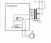
From this, it seems the transformer can be wired for differnt voltages. To my knowledge, this is set by either Rotel or the importer. It says 230Vac on the amp, as a "2 prong EU" plug and was bought new here in Norway. After 10+ years of good use, I'd imagine this is wired for 230V.
There is no switch for this as on some other types of equipment. The only switch on the amp, is the power/mains switch.
Last edited:
- Status
- Not open for further replies.
- Home
- Amplifiers
- Power Supplies
- Easing up inrush current buring relays in DIY trigger