Hi there! 🙂
I've got an issue here, hopefully someone can help me find an easy approach to this. My equipment is 230V. I'll give the issue at hand first for shorter read, and add the details and background below.
I have implemented a 12vdc/230vac relay circuit in my Rotel RB-985 PA for trigger control. For the basics function, this setup works well. No issues once powered up. There was very little space in the Rotel for mounting extra hardware, so I'm hoping to keep the timer/relay boards I'm currently using, as while they are small - they are a snug fit. The problem is - the inrush current of the of the large toroid transformer keep "welding" the relays in closed posisiton.
As it works well beyond this short inrush current, I was told to apply a "RC snubber" to the circuit. Now while I'm not completely inept, I'm still a novice with electronics. As far as I could understand, this resistor-(bipolar) capacitor combination goes "in" in parallel with the rest. But would it go in parallel with 230vac in/230vac out on the relay, or across the 2 phases after the relay (parallel to the "load" ?
I addition to the actual "placement" within the circuit - what are appropriate components? I already have a bag of 0.1uF 275VAC polyester film X2 type capacitors left over from a powerstrip filter project ( like these - but slightly lower voltage rating- are these suitable? I mostly know polarity-oriented DC capacitors, so this is new territory for me. And, what kind of resistor value and power tolerance would be suitable? This is obviously not a motor that goes on/off every few seconds.
So bacially - What sequence does the resistance-capacitor link go in, where does it go in, can I use the capacitors I have, and what resistor do I need?
---
My understanding is that a NTC solution (wich I don't completely understand the composition of), would vary its resistance with current throughput and be affected by ambient temperature. the passively cooled Rotel RB-985 gets proper hot as is, and the "normal" operating current obviously also vary quite a lot.
I've built a time-delayed trigger circuit for the PA, so it will power up a few seconds after my AV receiver (on which I cannot set any trigger delay). To save some space and time, I went with 2 "complete" timer modules with SPDT 12vdc/230vac relays, one for each phase line (as I couldn't find a suitable module with a DPDT/DPST relay). Due to power consumption of the timer circuit and 100mA max on the AVR trigger output(12vdc), I cut the traces for the timer circuit on the second module, and soldered the 12vdc relay inputs from the module with timer intact, to the module with the timer "cut away".
The reason I went with this delay routine, is that the AVR sends the trigger signal the moment fires up the transformer and starts charging its banks - and the Rotel PA has no soft-start circuitry and will blink the lights pretty hefty for a few ms (16A power circuit) when powering on. Without the delay, the amps will occacionally pop the mains fuse when powered on simultaniously. These are quick-fuses, and due to regulations and my place being a rental, I cannot change them. The previous owner would occacionally pop his 10A fuse when powering on the Rotel RB-985 alone.
I tried doing a mock-up of the circuit as I understood it - hopefully anyone can correct me if I got something wrong. I already explained the reason for going with 2 separate SPDT relays (wired for use "as" SPST, Normally Open).

Last edited:
Capacitors must be X2 rated for this and suitable for your line voltage. Don't even think about using a 400vdc "ordinary" cap, they can and will fail. Even 630 vdc aren't safe on mains and were a regular failure item back in the day.
I have my doubts that a snubber will work reliably tbh. If the contacts are welding together then it suggests the relay is hugely under rated. You may well need a 30 amp component for long term reliability here.
I have my doubts that a snubber will work reliably tbh. If the contacts are welding together then it suggests the relay is hugely under rated. You may well need a 30 amp component for long term reliability here.
I am prepared to use larger, 30A relay(s) and re-design the layout if I must - although I'm hoping to not have to. I guess this is mostly down to component space being in short supply, and if going with larger relays I have to redesign and make a completely different timer solution. I have most parts available close by, so I'm hoping to try the snubber route with the current relays (https://dl.dropboxusercontent.com/u/33963407/datasheet_relay.pdf) first. I do 2-phase break, one relay per line. If the relays weld again after that, I'll find some way to make room for larger relays etc.
So my line/mains voltage is 230VAC. the capacitors I do have here, are X2-type, rated 275VAC and 0.1uF (100nF). Can I use these you think?
If so - I'm left with finding an appropriate resistor value (Resistance and wattage). And - I'm still a bit unsecure where the RC snubber goes in (parallel to the relay input/output - or parallel to the actual load (after relay)). I understand how it can protect the relay from arcing/inrush current if parallel over the relay coupling - but I heard the snubber can also go parallel over the load - and this way I avoid any current leak when the relays are open (amp "off"). What I don't get, is how this would ease the inrush current through the relays.
If it will do the job, I wuld of course prefer the latter method - as I would only need a single snubber, instead of one for each single-pole relay.
Perhaps a NTC resistor is appropriate - as it should introduce a substantial resistance at turn-on (wrt the in-rush peak). You would need to determine the nominal operating current in order to select the NTC device. An NTC could be put in to both your equipments, and may remove the need entirely for delay relays.
The other way is to use an addition delay relay with a longer delay time, and use that extra relay to short out a 'soft-start' resistor that would be in series with the transformer primary.
The contact welding may be alleviated by also placing a MOV across the primary, so as to take some energy out of the transformer winding that is wanting to keep current flowing during relay contact bouncing on turn-on. An RC across the primary winding would be somewhat similar function, and an NTC series device would also be helping.
Last edited:
Thank you. While the Rotel PA is a fairly straight-forward design which I can to some degree comprehent throught the service manual - The NAD AV receiver is a totally different story, and it does incorporate a "soft start" sequence, albeint not quite soft enough for simultanious power-on of both the AVR and the Rotel PA. This is why I'm trying to remedy the issue at the "PA end".
NTC resistor - wouldnt that be best suitable for a more or less constant current draw? A typical "home entertainment" PA is anything but that..(?)
As far as I could read, a MOV would do nothing in terms of inrush current "easing" / protection - but I might have misunderstood either what I read or what you're implying.
Im just trying to find an easy and echonomic way ease the inrush current to a level where the relays can operate normally. Again, quite the novice. I'm not stuck on one path - but I'm quite short on internal component space (external is a no-go, already did panelmounts of trigger connection and switch for Trigger/normal operation) and a a bit low on dough.
I really appreaciate the help here - i just might not be quite up to speed.. 🙂
Contact welding occurs when the contact bounces at turn on. During a bounce, the contact tries to open but the inductive energy on the primary keeps pushing current through the contact, albeit in an arc. The energy in the arc is what exacerbates the molten contact point and welding aspect. The arc results from the primary winding voltage flying high enough to initiate and sustain the arc even though the contacts have momentarily separated. The MOV, or RC snubber, bypasses energy that would otherwise cause the winding voltage to fly even higher.
The NTC has a cold resistance that has an impact on the inrush current waveform. It will get hotter and the resistance drop for normal operating current of the amp, up to a maximum operating current level (which is from the amp spec).
The NTC has a cold resistance that has an impact on the inrush current waveform. It will get hotter and the resistance drop for normal operating current of the amp, up to a maximum operating current level (which is from the amp spec).
So an RC snubber (I do believe I closing the grasp on that one now) (does series sequence count?) -, for a short instance, it absorbs the energy that causes the voltage and amperage to fly high enough to cause the "welding arc" during the relay contact bounce..? or does it "absorb" any excess energy/voltage spike beyond that again - basicly not doing much to dampen the spike that causes the relay bounce arc in the first place..? Or would it basically absorb the excess inrush current, taking (if appropriate components used) "the hit" for the relays during that short instance the "bounce" would occur...?
The relays get 12vdc "trigger voltage" after set delay, although they don't "click" any more - they're just stuck/welded in closed posisiton.
If the latter is the case, I'm inclined to go with the RC snubber route - as I have the previous mentioned X2 0.1uF 275VAC capacitors already, and a friend nearby has some 22ohm 5W resistors lying about. (I'm still not sure if these will suffice, but hope so). If I have understood correctly, if as to "ease up on the relays" - the RC snubbers goes parallel over the AC in/AC out relay connection.(?) The relays are 12vdc triggered.
Or did I completely mis understand, and the snubber goes over "the mains", after the relays?
I'm not quite sure how the NTC solution goes into the circuit to "shield" the relays. The amp is driven off 230v mains - the power rating for it is ~500WRMS, 850W max draw (this all acounts for "normal" operation, not power-on). the internal mains fuses are rated 6.3A (again, 230VAC). I've tried reading a bit on NTCs, but it seems even selecting an appropriate component is quite a daunting task. Its been 15 years since I did a 6-month basic electric/electronic course - now adays I couln't configure a NE555 if my life depended on it.... but I'm eager to learn (again) 🙂
Last edited:
Hi,
I agreed with trobbins suggestions of the use of an MOV. I would connect them across the relays contacts. Remembered you are turning on/off a transformer and to prevent arcs across the relay contacts you must close and open them as fast as possible to prevent the voltage arc across. I think that the MOV will prevent the arc across the relay contacts. For the MOV to do the work the voltage rating must be selected for the application. Since you are using 230 volts AC I would use one about 300volts across the contacts.
I agreed with trobbins suggestions of the use of an MOV. I would connect them across the relays contacts. Remembered you are turning on/off a transformer and to prevent arcs across the relay contacts you must close and open them as fast as possible to prevent the voltage arc across. I think that the MOV will prevent the arc across the relay contacts. For the MOV to do the work the voltage rating must be selected for the application. Since you are using 230 volts AC I would use one about 300volts across the contacts.
A CL60 costs $2 and is a simple solution. Just wire in line with the mains.
Gets hot during use that's normal/essential - just keep that in mind as you place it in the case. digikey link : Invalid Request
It has a resistance when cold of 10 ohms thereabouts and this limits the inrush current nicely. When hot, the resistance drops to less than an ohm.
If you wanted to get fancy, you can wire up one of the spare contacts to short the device after a little delay.
Last edited:
The inrush current waveform in to a transformer typically starts with very high current peaks - this is the time when the contacts are prone to bouncing. The NTC function is to suppress the initial peak levels due to the influence of its cold resistance, compared to the other circuit resistances in play. Hence the inductive energy that is pushing the arc is less.
If the fuse is 6.3A, and the power draw about 3A, I'd look for an NTC with a max continuous current rating of about 4-5A. The CL60 suits that.
If you have a good ohmmeter, you can measure the DC resistance of the mains input of the amp, and compare that with 10 ohm.
I would personally put a MOV or RC across the primary winding, as that is where the additional voltage is coming from to start or maintain the arc. The arc voltage can also come via the mains voltage, depending on what that is at the time of contact separation.
An NTC is not really appropriate for a class-b amplifier as it will modulate power. If you can bypass the NTC with a relay then it's suitable. But you are short on space.
See how you fare with the snubbing first.
See how you fare with the snubbing first.
An increased effective mains impedance would somewhat lower the peak rectifier currents, with a trade-off of probably slightly higher rms 2f ripple on the main filter cap, but probably a slightly lower crest factor on that ripple waveform.
The effective impedance of the filter cap to the audio signal loading would be way way lower than the effective impedance of the mains supply charging that cap for most amps I'd suggest, in which case NTC related modulation would be a poofteenth.
The effective impedance of the filter cap to the audio signal loading would be way way lower than the effective impedance of the mains supply charging that cap for most amps I'd suggest, in which case NTC related modulation would be a poofteenth.
I would try an X2 cap, not a snubber. Your aim is simply to reduce the voltage developing across the temporarily open contacts. Capacitance does this; resistance simple adds a bit more voltage. The reason a snubber includes resistance is that if the contact is to remain open you need some way to dissipate the energy. Your contact will be closing again.
I would put the cap across the transformer primary. This will lengthen its life, as it will only be subjected to mains voltage when the item is switched on. One cap can protect both switch poles.
I would put the cap across the transformer primary. This will lengthen its life, as it will only be subjected to mains voltage when the item is switched on. One cap can protect both switch poles.
As this is a fairly heavy-duty unit to be fondling inside of while "on-line", and my hands aren't rock steady - I've done my measurements with the amp disconnected from mains. Bare in mind, the "control" for the PA is a mecanical on/off breaker - so for the "DIY" trigger to work - the breaker needs to always be in the "on" position. As I was unable to figure out, both through visual inspection and the service manual - wether the breaker do single or double pole break - I went "the safe route" with a double pole break at the "DIY trigger" relays.
@trobbins: I have a pretty decent multimeter, altbeit only needle probes - thus difficult to do current measurements (I was hoping to be able to measure the current spike at power-on, but the digital display simply doesn't update fast enough). I got a set of mixed brobes and clamps off ebay, but the plugs were both too narrow (3.5mm) while my meter takes 4.5mm plugs. I don't want to "bulk up" the plugs, as the product of that would likely affect readings.
With the PA panel breaker in "ON" posistion (has to be for trigger to work), I'm getting 1.2 ohms over the mains to the panel breaker(-> toroid trafo).
I'm getting strongly mixed messages here in regards to NTC - suitable/not very suitable - across the relay terminals (wouldn't this cause a small current draw at all times, even with the trigger/relay open(off))? , across the mains (between relay output and panel breaker(->toroid trafo), in line with mains (before or after relay?)
@richie00boy - if going the snubber route - do the RC snubber go parallel with the relay (slight "drip" while relays are open/amp off - due to panel breaker always closed)? Or does it go between the mains, after the relays? And do you think the X2 capacitors linked below paired with 22ohm 5W resistors will do?
@DF96 - if an X2 cap alone could do the job (across the trafo primary you say... would across the mains, after relay "output", suffice?) - do you think -these- would do? I have like 15 of these - well, equvalents, but rated 275VAC not 400VAC as those linked (mains voltage 230Vac). If this would reduce the voltage spike across the bouncing relay contacts, this sounds like the simplest solution by far - as I already have like-for-like relays on the way, and those X2 caps (if suitable) I have plenty of already. Aaand, it most definitely is the route that takes the least space.
If of any use, a few resources:
Amp manual: https://dl.dropboxusercontent.com/u/33963407/rb985_eng.pdf
Amp service manual: https://dl.dropboxusercontent.com/u/33963407/Rotel_RB-985_service_manual.pdf
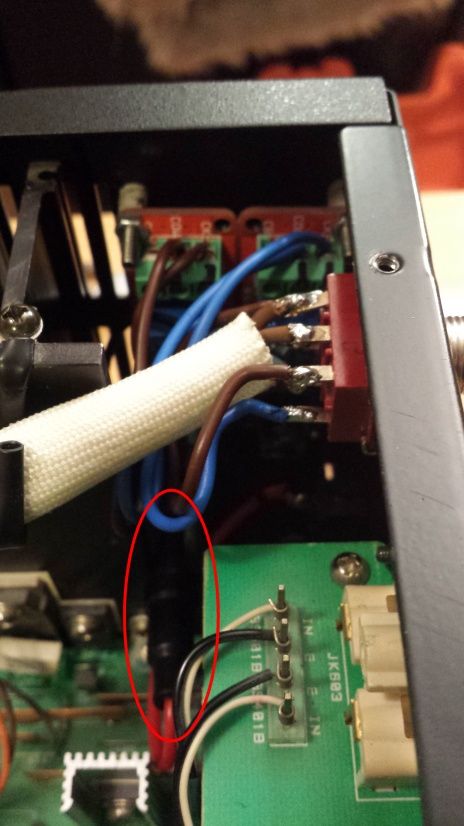
This is the space I have to work with (the circled area is just a 100mA inline fuse for the trigger, as I couldn't get a decent answer from NAD wether the trigger output was fused or not, only that max output was 110mA 12vcd) - - And yes, its wired through a toggle switch, so as to be able to toggle between triggered operation and "manual". And yes, I laquered the mounting surfaces of the relay/timer boards and used plastic standoffs, as to not pick up any accidental ground. The amp is not mains grounded. :
@trobbins: I have a pretty decent multimeter, altbeit only needle probes - thus difficult to do current measurements (I was hoping to be able to measure the current spike at power-on, but the digital display simply doesn't update fast enough). I got a set of mixed brobes and clamps off ebay, but the plugs were both too narrow (3.5mm) while my meter takes 4.5mm plugs. I don't want to "bulk up" the plugs, as the product of that would likely affect readings.
With the PA panel breaker in "ON" posistion (has to be for trigger to work), I'm getting 1.2 ohms over the mains to the panel breaker(-> toroid trafo).
I'm getting strongly mixed messages here in regards to NTC - suitable/not very suitable - across the relay terminals (wouldn't this cause a small current draw at all times, even with the trigger/relay open(off))? , across the mains (between relay output and panel breaker(->toroid trafo), in line with mains (before or after relay?)
@richie00boy - if going the snubber route - do the RC snubber go parallel with the relay (slight "drip" while relays are open/amp off - due to panel breaker always closed)? Or does it go between the mains, after the relays? And do you think the X2 capacitors linked below paired with 22ohm 5W resistors will do?
@DF96 - if an X2 cap alone could do the job (across the trafo primary you say... would across the mains, after relay "output", suffice?) - do you think -these- would do? I have like 15 of these - well, equvalents, but rated 275VAC not 400VAC as those linked (mains voltage 230Vac). If this would reduce the voltage spike across the bouncing relay contacts, this sounds like the simplest solution by far - as I already have like-for-like relays on the way, and those X2 caps (if suitable) I have plenty of already. Aaand, it most definitely is the route that takes the least space.
If of any use, a few resources:
Amp manual: https://dl.dropboxusercontent.com/u/33963407/rb985_eng.pdf
Amp service manual: https://dl.dropboxusercontent.com/u/33963407/Rotel_RB-985_service_manual.pdf
This is the space I have to work with (the circled area is just a 100mA inline fuse for the trigger, as I couldn't get a decent answer from NAD wether the trigger output was fused or not, only that max output was 110mA 12vcd) - - And yes, its wired through a toggle switch, so as to be able to toggle between triggered operation and "manual". And yes, I laquered the mounting surfaces of the relay/timer boards and used plastic standoffs, as to not pick up any accidental ground. The amp is not mains grounded. :
Last edited:
An X2 cap will always say X2 on the cap and in the catalogue and in the datasheet. An AC voltage rating is not sufficient. It must say X2. Those do not, as far as I can see.do you think -these- would do?
After a closer inspection on the linked specs for the caps I substituted (couldn't get my hands on the Vishay caps when I needed these), I do notice their specs are lacking. The online specs I could find for the ones I do have are as useful as specifying a power supply as "slighly heavy". Captain hindsight strikes again.
These are the ones I actually do have - clearly X2 marked. I still have a feeling I can't just use any x2 cap - so it is important to know if these should suffice for intended use (and if wired across mains after relay output is adequate).
These are the ones I actually do have - clearly X2 marked. I still have a feeling I can't just use any x2 cap - so it is important to know if these should suffice for intended use (and if wired across mains after relay output is adequate).
An externally hosted image should be here but it was not working when we last tested it.
Last edited:
0.1uF X2 is suiatble for connecting across the mains, Live to Neutral.
DO NOT connect an X2 Protective Earth to Live, nor to Neutral.
This duty requires Y2, or better.
DO NOT connect an X2 Protective Earth to Live, nor to Neutral.
This duty requires Y2, or better.
So, these would suffice, and they go in across the mains (live to neutral) after the relays? Would a single one suffice?
I got these X2 caps for a 7-outlet power-strip project, so I have done the read-up on the basic do's and don'ts on X / Y caps in terms of Live->neutral (X) and live/neutral->ground (Y). The power strip (Through which the PA is connected) already have one of these across every outlet - but I guess these are on the "wrong side" of the triggered relays. I Don't really know what these can/can't do beyond this though - thus the "questionare".
I did a modification to my "rough schematic", introducing the X2 cap (Green). Would this be correct placement? Only a single one of these caps?
I have mentioned this earlier, but as it could be essential informationt; Due to the design and limited selection of the timer/relay modules, I had to go with 2x SPDT relay modules. I cut the traces for the delay timer circuitry on one module (and linked the 12v/gnd inputs on the relays. This was done to both keep a safe margin from the 100mA 12vdc limit of the AVR trigger outout. And not risk misaligned delay adjustments on the separate modules. The timer adjustment is mechanical - amd A single timer/relay module pulls ~65mA - adding just the relay of the second module sums to a little less than 90mA.
Again, in hindsight - as the amp is not mains grounded - i could possibly get away with only a single phase break..? I Do have an intact spare "timer module" (http://www.ebay.com/itm/371016953107)
I did "scetch in" the RC-snubbers previously, set up as far as I could comprehend it at that point in time. Component values for the snubbers are "for illustration purposes" at best, as thats what I have on hand, and still got no answer regarding series sequence (if it matters), or actual approriate specs. I did an eBay search for snubber caps, and most hits came up with rather huge, $15 1200V caps.
Would these snubbers be redundant if using just the X2 cap across live & neutral, after the relay(s)? And if it is still advisable/necessary to add the RC snubbers - would this be the correct implementation/sequence?
I got these X2 caps for a 7-outlet power-strip project, so I have done the read-up on the basic do's and don'ts on X / Y caps in terms of Live->neutral (X) and live/neutral->ground (Y). The power strip (Through which the PA is connected) already have one of these across every outlet - but I guess these are on the "wrong side" of the triggered relays. I Don't really know what these can/can't do beyond this though - thus the "questionare".
I did a modification to my "rough schematic", introducing the X2 cap (Green). Would this be correct placement? Only a single one of these caps?
An externally hosted image should be here but it was not working when we last tested it.
I have mentioned this earlier, but as it could be essential informationt; Due to the design and limited selection of the timer/relay modules, I had to go with 2x SPDT relay modules. I cut the traces for the delay timer circuitry on one module (and linked the 12v/gnd inputs on the relays. This was done to both keep a safe margin from the 100mA 12vdc limit of the AVR trigger outout. And not risk misaligned delay adjustments on the separate modules. The timer adjustment is mechanical - amd A single timer/relay module pulls ~65mA - adding just the relay of the second module sums to a little less than 90mA.
Again, in hindsight - as the amp is not mains grounded - i could possibly get away with only a single phase break..? I Do have an intact spare "timer module" (http://www.ebay.com/itm/371016953107)
I did "scetch in" the RC-snubbers previously, set up as far as I could comprehend it at that point in time. Component values for the snubbers are "for illustration purposes" at best, as thats what I have on hand, and still got no answer regarding series sequence (if it matters), or actual approriate specs. I did an eBay search for snubber caps, and most hits came up with rather huge, $15 1200V caps.
Would these snubbers be redundant if using just the X2 cap across live & neutral, after the relay(s)? And if it is still advisable/necessary to add the RC snubbers - would this be the correct implementation/sequence?
Last edited:
One X2 cap after the relays should do the trick. No need for snubbers too.
You need to be cautious. High power circuitry has its own challenges, including safety.
You need to be cautious. High power circuitry has its own challenges, including safety.
Thank you dear sir 😉 This (0.1uF,275vac) x2 cap goes across live and neutral, right?
I'm taking most precautions I can think of; Grounded work surface and armlink, give the equipment atleast a few hours of time disconnected from mains before even cracking the chassis. I usually work with rubber electrician gloves when anywhere near mains or high-current ac/dc - and stay well clear of the cap banks as much as I can.
Any other tips on this?
- Status
- Not open for further replies.
- Home
- Amplifiers
- Power Supplies
- Easing up inrush current buring relays in DIY trigger