I've just built a pair of MX50 amps with Sanken (Chinese copies) O/P devices:2SA1295Y, 2SC3264Y
The amps work perfectly until I attach the O/P devices to the heatsink, the amps then develop hf oscillation on top of the applied test signal. If I isolate the heatsink from earth the oscillation stops and the amps work as normal. I don't like having the metal work of the heatsink floating and I'm not confident that the stability will remain even if I do. Anyone have experience of this phenomenon?
The amps work perfectly until I attach the O/P devices to the heatsink, the amps then develop hf oscillation on top of the applied test signal. If I isolate the heatsink from earth the oscillation stops and the amps work as normal. I don't like having the metal work of the heatsink floating and I'm not confident that the stability will remain even if I do. Anyone have experience of this phenomenon?
Thanks, yes, I tried that, but it just damps it a bit. Also that seems like a sticking plaster instead of addressing the root cause.

I assume you mean different, smaller, output devices? Well, that is an option to try. I guess it is a Chinese kit, so maybe they never tried these devices properly in circuit, mounted in an earthed chassis.
Thanks rayma I will try that. I found that if I put my finger on R6, 2k2, between Q1/Q3/Q4, it temporarily stops the oscillation.
What is the frequency of the oscillation? Does it matter if you are driving a load? If driving a load...is it worse on positive or negative half?
I notice no small caps in parallel with the output bypass caps. Does it get better or worse adding 0.1 uF across them?
The answers to those questions might give us some more hints...
I also notice there is not a damped output inductor...I don't think it's a part of this problem, but should be a part of any amp that you want to be generally stable.
Thanks rayma I will try that. I found that if I put my finger on R6, 2k2, between Q1/Q3/Q4,
it temporarily stops the oscillation.
Be sure to use a COG/NPO type for C11. I do worry about the lack of an output inductor.
Only the most well designed amplifiers can be used without one.
I take it the heatsink is directly connected to the circuit earth ?
If so and you are using the correct version of 2SA1295 then the collector is connected to the heatsink so I also take it you have insulated it from direct contact with the heatsink and there is no leakage ?
If there is zero leakage (resistance wise ) then you might have capacitance between the heatsink and the BJT.
If it is not too big a job isolate the heatsink from the earth using a 10ohm resistor then try again.
These are just tests and I am not implying anything as other conditions could apply like a lower standard of BJT manufacture but just tell me if you have eliminated those checks ?
Something else to consider when you get the problem solved -
R30 and C14 have a short across them, likely a missdrawn schematic.
R30 and C14 have a short across them, likely a missdrawn schematic.
djoffe, I'll try those things when I get back to the bench. Thanks. It is on both pos and neg halves and only under load, 4 or 8ohm. I did try an output inductor, but to no avail. Cheers. Matt
It is on both pos and neg halves and only under load, 4 or 8ohm.QUOTE]
Then do try increasing the value of C11.
Even with an output inductor, it still oscillated under load?
one quick question:
value of R24?
other trouble-shooting issues:
can you upload corrected schematic?
next interesting question: is this a loop gain issue, or an output stage oscillation issue? What happens to the oscillation if you take R17 down to 470/2=235, say by paralleling R17 with another 470 Ohms?
value of R24?
other trouble-shooting issues:
can you upload corrected schematic?
next interesting question: is this a loop gain issue, or an output stage oscillation issue? What happens to the oscillation if you take R17 down to 470/2=235, say by paralleling R17 with another 470 Ohms?
OK guys, a few things to try there! I'll let you know when I've checked. That schematic is the one I have. I've not reversed engineered to check it as yet.
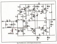
I thought I recognised that circuit looks like a standard D.Self power amplifier layout especially the value and placing of the Comp. capacitor he has changed some components in later designs .
HIGHLY unusual that a D.Self design has oscillation you sure the compensation components are okay and don't remember the two diodes connected to the output never seen that in a DS design ??
Well not at least in the pages of EW where he put his ideas to in the 1980,s on and I have seen plenty of his designs .
- Home
- Amplifiers
- Solid State
- Earthed heatsink causes hf oscillation