@Scott You answered meWow, more interesting.
The relashionships of BJT parameters and the reasons why. Thanks, this is right on what I am looking for.
Is it possible to go a step further about Beta versus Va ( Early voltage ) with a quantitative relashionship. Stating for instance: A +5% Beta goes with a +5%Va ?
I do not know what "Sze" means.Sorry it's not that specific, you would need to consult the standard texts on this like Sze.
Indeed, my +5% bit makes no sens. As a second thought:
I understand Beta and Va are mostly related from the base junction width. So a pair of BJT matched for Beta will match for Va.
To go beyond that, to know what goes on about a x% beta increase, I think there is a relashionship of this kind.
For a +x% Beta, there is +K*x% Va.
The reason is from maths: Beta is some function of junction width, Va is some other function of junction width, there is no reason for these two functions to be linear, however around a base junction width value ( or Beta value ), we can linearize. Hence there exist such a K value in a given Beta vicinity.
That's all the maths can tell, there exist such a K, it only gives a framework.
With measures over a lot of BJTs from the same batch, one could fully characterize the Beta Va dependancy with a plot of this K versus Beta. There is no reason for K to be 1 neither be positive or negative nor valid over other BJT models. It is up to this BJT and it's manufacturing to decide whether that K is more or less constant or varies with Beta.
Knowing this Beta Va dependency would help in my design.
Sze is the surname of a physicist who worked at Bell Labs, full name Simon Min Sze.
He wrote an authoritative book entitled "Physics of Semiconductor Devices" and whenever a semiconductor guy (like Scott Wurcer) mentions "Sze", it is simply shorthand for "Simon Sze's encyclopedic book, PoSD".
Then Dr Sze returned to Taiwan, and has issued a couple of new revised editions since then.
An interesting debunk.I got interested in Early voltage a while back, and published some, not all, of my measurements in this thread:
Measuring the Early voltage "VA" of some PNPs at 8mA
Lots of people made the same bold assertion in follow up postings: (Beta times EarlyVoltage) is a constant!! They are inversely proportional!! It's all directly related to VceMax. Duh!!
So I created a scatterplot of my measured data. See below. I only measured one transistor of each part#; if that's not what you were hoping for, I am sorry.
For the transistors that I measured, Vearly varied over about a 12-to-1 range, while (Beta*Vearly) "only" varied over a 6-to-1 range. Which is not a very good approximation of a constant, in my opinion.
_
A study over different BJT models that shows (Beta*Vearly) is NOT constant.
Among BJTs from the same batch, who knows, may be ( and why ), may be not ?
The main source of distortion in modern amplifiers is the output stage. Amplifier theory is advanced that Input and VAS distortions are negligible when compared to the output stage distortion in any modern design. It's the output stage crossover distortion that is the major contributor to any competently designed modern amplifier.
Totally agree!!!!
The main source of distortion in modern amplifiers is the output stage.
Totally agree!!!!
Are you really joking?
Let me totally break your patterns - absolutely and qualified NO.
While properly developed AB-class OPS have intrinsic distortion at an order of -50-60 dB then your best last high-voltage VAS stage have THD figures at order of -30-40 dB simply due to Early effect.
Being even more really - the main method to minimize both of that distortion effect are the same - tons of feedback. So working on good OPS THD figures simultaneously includes work on good VAS THD figures, but there are very different effects for each of them.
Bipolar OPS needs to be properly biased and switched off with fast minor carriers extraction. Or you'll pick all bad from the shoulders crossover.
MOSFET OPS needs to be precisely transconductance matched. Or you'll pick all bad from shoulders non-uniformity
Last VAS stage must be based on low-Early trannies with good voltage margin (>20V). Or you'll pick all bad from huge Early-related distortion at orders of 10-30% THD.
The main source of distortion in modern amplifiers is the output stage. Amplifier theory is advanced that Input and VAS distortions are negligible when compared to the output stage distortion in any modern design. It's the output stage crossover distortion that is the major contributor to any competently designed modern amplifier.
Ill take that as harmonic distortion.
Dont think so. Crossover distortion is usually the most detrimental because its very high order (7th harmonic) but the levels are usualy lower than first 3 harmonics.
But a major contributor to an overall 0.001% distortion figure is not a major issue!
Maintaining accurate bias over time and across changes in temperature and load so that 0.001% figure really represents the amp in use is to me more of an issue - low crossover distortion relies on accurate and stable bias with BJT outputs, as well as sufficient NFB.
My take on distortion is setup a test with a whole bunch of tones that aren't harmonically related and look at the total harmonics and intermodulation products - more power in such products means worse amplifier. Crossover distortion is going to make lots of products, so its nastier character is automatically compensated for?
So I've simulated this using Python's signal processing module (part of scipy), input and distorted spectra shown - intermodulation products proliferate due to the large number of combinations of 2 or 3 tones being mixed together.


(2nd and 3rd harmonic distortion modelled).

(higher order harmonics (at a lower level) modelled to approximate crossover distortion)
Maintaining accurate bias over time and across changes in temperature and load so that 0.001% figure really represents the amp in use is to me more of an issue - low crossover distortion relies on accurate and stable bias with BJT outputs, as well as sufficient NFB.
My take on distortion is setup a test with a whole bunch of tones that aren't harmonically related and look at the total harmonics and intermodulation products - more power in such products means worse amplifier. Crossover distortion is going to make lots of products, so its nastier character is automatically compensated for?
So I've simulated this using Python's signal processing module (part of scipy), input and distorted spectra shown - intermodulation products proliferate due to the large number of combinations of 2 or 3 tones being mixed together.
(2nd and 3rd harmonic distortion modelled).
(higher order harmonics (at a lower level) modelled to approximate crossover distortion)
Last edited:
To measure Va, I see no other way than based on the definition of the Early voltage as seen on this idealized graph.Yes, and your graphs can even be used easily to obtain the early voltage. Just extend a Vce/Ic line to the left and see where it crosses the neg voltage axis. That's your early voltage.
(The graph is from Peter Baxandall in Linear Audio | your tech audio resource and illustrates the early voltage distortion effect)
Jan
Who knows, how these extended Vce/Ic ( at some Ib ) actually "cross" around some point ? It is more a cloud than a point !
Bob Cordell mused about how to build a test jig to measure Vearly, in the thread whose title is (approximately!) "Bob Cordells amplifier book"
He very well might have done so, and put his design in the 2nd edition of his book which is coming out in the next 1-3 months. We'll soon know.
If my memory is correct, Bob's idea was based upon measuring AC impedances. According to the small signal hybrid pi model of a BJT, the impedance looking into the collector of an undegenerated common emitter amplifier, is ro = [(Vearly + Vce)/Ice]. Build a fixture with known and constant Vce and Ice, measure impedance ro. Then crank the arithmetic to calculate Vearly given Vce, Ice, and ro. Done.
No doubt, that is the way to proceed. This applies the definition of the Early voltage seen on Vce Ic graphics and no need for a book.Bob Cordell mused about how to build a test jig to measure Vearly, in the thread whose title is (approximately!) "Bob Cordells amplifier book"
He very well might have done so, and put his design in the 2nd edition of his book which is coming out in the next 1-3 months. We'll soon know.
If my memory is correct, Bob's idea was based upon measuring AC impedances. According to the small signal hybrid pi model of a BJT, the impedance looking into the collector of an undegenerated common emitter amplifier, is ro = [(Vearly + Vce)/Ice]. Build a fixture with known and constant Vce and Ice, measure impedance ro. Then crank the arithmetic to calculate Vearly given Vce, Ice, and ro. Done.
Maths cranked: Vearly = ro x Ic - Vce
Last edited:
The direct and naive methods of measuring Vaf (or Var) detailed in this thread are not necessarily the simplest, most accurate or most effective.
As a food for thought, you could for example meditate on this simulated jig:
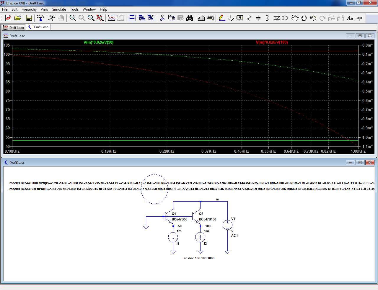
Some time ago, I became interested in the Early effect, and in particular its dependence on parameters like Vce or Ic, to better understand their effects on higher-order non-linearities
I decided to build myself a complete Vaf test set, to properly investigate.
I built a true and complete lab instrument, using an original algorithmic, charge-pump method of measurement, where the DUT itself is part of a dedicated A-to-D converter.
It measures Vearly between 0 and 1000V, with a 4-digit or 0.1V resolution, for P or N devices and the Vce can be set anywhere between 0 and 100V, and the Ic from a few nA to 100mA.
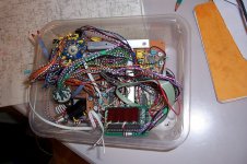
In the end, it was perfectly working and calibrated, and I made a few real test runs, only to realize that such refinements were in fact completely unnecessary: Vaf is just a single, convenient and scalar value but it is a rough metric incorporating a number of phenomenons.
This is why I didn't even care to put the instrument in a case: not that it is completely useless, but a much simpler and less accurate instrument would be ample enough for the task, and I shelved this one.

As a food for thought, you could for example meditate on this simulated jig:
Some time ago, I became interested in the Early effect, and in particular its dependence on parameters like Vce or Ic, to better understand their effects on higher-order non-linearities
I decided to build myself a complete Vaf test set, to properly investigate.
I built a true and complete lab instrument, using an original algorithmic, charge-pump method of measurement, where the DUT itself is part of a dedicated A-to-D converter.
It measures Vearly between 0 and 1000V, with a 4-digit or 0.1V resolution, for P or N devices and the Vce can be set anywhere between 0 and 100V, and the Ic from a few nA to 100mA.
In the end, it was perfectly working and calibrated, and I made a few real test runs, only to realize that such refinements were in fact completely unnecessary: Vaf is just a single, convenient and scalar value but it is a rough metric incorporating a number of phenomenons.
This is why I didn't even care to put the instrument in a case: not that it is completely useless, but a much simpler and less accurate instrument would be ample enough for the task, and I shelved this one.
Attachments
Elvee, I like this differential way to measure Va. I assume one of the two transistors is a reference with known Va.
_This jig shows the trouble made by Va mismatch in a balanced two transistors circuit like a LTP. Va mismatch clubbers Common Mode Rejection Ratio. This jig goes directly at measuring CMRR.
_It is a good jig to match transistors on Va. Constant current sources are not necessary, you can do with matched resistors ( just a bit more calculus to extract Va).
There is no need for complexity.
2 matched resistors, a power supply, a LF generator ( PC with sound card ) and a DVM.... and a bag of transistors.
Last edited:
Yes, that is something my cheapo, 1970 Levell microvoltmeter does easily and routinely, but this was just food for thought: it shows that simple alternative methods do exist, and can work quite well when used sensibly.A meter that reads microvolts AC.
I didn't opt for that one, but using "modern" (note the quotes) synchronous techniques, nV or even sub-nV levels should be accessible, even with a properly used, humble CD4053.
I am not even mentioning the likes of the LTC1043, or their more modern versions
The jig does not show the differential value, it shows the absolute value for two different and known (50V and 100V, artificially created) transistors.Elvee, I like this differential way to measure Va. I assume one of the two transistors is a reference with known Va.
_This jig shows the trouble made by Va mismatch in a balanced two transistors circuit like a LTP. Va mismatch clubbers Common Mode Rejection Ratio. This jig goes directly at measuring CMRR.
_It is a good jig to match transistors on Va. Constant current sources are not necessary, you can do with matched resistors ( just a bit more calculus to extract Va).
There is no need for complexity.
2 matched resistors, a power supply, a LF generator ( PC with sound card ) and a DVM.... and a bag of transistors.
You can note that the resulting voltages are not exactly 50V and 100V. That is the result of the simplicity and crudeness of the test-jig for one, and the fact that in reality Vaf is a nice theoretical shortcut for things more complex, also dependent on other parameters that even spice models take into account.
However, for differential measurements, these subtleties mostly vanish, and you can just rely on the difference for matching, provided you have done your homework first, ie. you only test devices having already passed the basic DC matching tests like Hfe, Vbe@ a defined Ic.
Since all parameters tend to be heavily correlated, you should get a good match rather easily if this condition is met (for a given process, of course).
That said, I do not think such a fine matching will bring a big advantage, apart from better even harmonics cancellation.
If you want to measure extremely small differential voltages, synchronous techniques are the way to go, and they can be implemented either using pure hardware methods like analog switches, or software methods based on a sound card.
For the latter, member Edmund Stuart is probably one of the best experts on this forum ... let's hope he stumbles on this thread...
I am striving to know better about this.Since all parameters tend to be heavily correlated, you should get a good match rather easily if this condition is met (for a given process, of course).
So far I know
_Hfe and Vbe do not.
_Hfe and Vearly do.
What about all parameters as listed in BJT Spice models ?
Does it make sense to assume BF / BR and VAF / VAR are heavily correlated ? May be there are more parameter pairs of this kind.
My quest is to generate realistic un-matched transistor pairs for Spice simulations where the point is to deal with the realities of not so well matched pairs.
- Status
- Not open for further replies.
- Home
- Amplifiers
- Solid State
- Early effect in LTP