Today my large capacitor mounts came in and I can start my build this weekend. Here is a pic of a few of them with the caps.

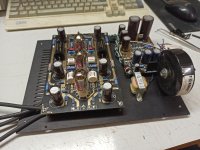
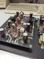
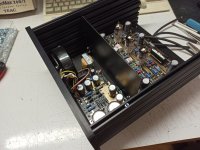
Today I finally put the preamp portion of the all out EAR 834P in my Clone enclosure that I bought a while back. I did this to get an idea of how this all out build will sound. I was really surprise Upon power up and after 20 mins of warm up, this build is way better than the one I fully tweaked out that I have been using.
This build has both the upgraded power supply and preamp board with the Jensen Copper Foil PIO caps. The sound stage is bigger, wider, and deeper. It has that gorgeous mids that the Jensen caps are known for. This reminds me a lot of the BAT VK-P10 phono preamp that I heard and loved so much years ago. Vocals, strings and horns are just so nice. The other Clone that I had been using was really nice but sound thing at times, this new all out build is totally different with more natural presentation.
So I will use the Solen Film Caps for the Power Supply 220uF and 330uF caps in the final build. The Caps I'm using now for all PS Caps are EPCOS.
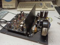
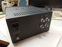
So now that I got a good idea of what this preamp is going to sound like, I can now move on to the building of the enclosure for this all out build. I was going to mount the Antek Transformer inside but I will put it in a separate enclosure and run an Umbilical Cord to the main preamp enclosure. I will mount the power supply pcb inside the main preamp enclosure as well.
Still thinking of how I will layout the front panel, I will check out some gear and see what I will do.
This build has both the upgraded power supply and preamp board with the Jensen Copper Foil PIO caps. The sound stage is bigger, wider, and deeper. It has that gorgeous mids that the Jensen caps are known for. This reminds me a lot of the BAT VK-P10 phono preamp that I heard and loved so much years ago. Vocals, strings and horns are just so nice. The other Clone that I had been using was really nice but sound thing at times, this new all out build is totally different with more natural presentation.
So I will use the Solen Film Caps for the Power Supply 220uF and 330uF caps in the final build. The Caps I'm using now for all PS Caps are EPCOS.
So now that I got a good idea of what this preamp is going to sound like, I can now move on to the building of the enclosure for this all out build. I was going to mount the Antek Transformer inside but I will put it in a separate enclosure and run an Umbilical Cord to the main preamp enclosure. I will mount the power supply pcb inside the main preamp enclosure as well.
Still thinking of how I will layout the front panel, I will check out some gear and see what I will do.

EAR834 is great preamp.
Attachments
-
 IMG_20220407_134833.jpg149.4 KB · Views: 150
 -
 IMG_20220407_134840.jpg435.3 KB · Views: 153
 -
 IMG_20220407_143518.jpg391.2 KB · Views: 151
 -
 IMG_20220407_143523.jpg412.5 KB · Views: 149
 -
 IMG_20220407_144929.jpg423 KB · Views: 142
 -
 IMG_20220407_233419.jpg288.2 KB · Views: 143
 -
 IMG_20220407_233453.jpg278 KB · Views: 148
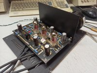
All I can say is WOW! this new build is really really good! way better than the fully upgraded/modded preamp PCB I had in it before.
I'm using Jim Hagerman's Inverse RIAA module to speed up the break in and I can hear in REAL time how the New Phono preamp started out and where its at now. I'm really happy how this build came out.
I'm using Jim Hagerman's Inverse RIAA module to speed up the break in and I can hear in REAL time how the New Phono preamp started out and where its at now. I'm really happy how this build came out.
So, that big green PSU resistor (1k R I think?) in the CRC power supply went up on my two box vlone today. I walked away while Bing Crosby was belting out some Christmas toons. And when I came back the record was looping in the runout, and something smelled bad. No sound on trying to put the needle back on the beginning of the record. Smell was coming from the PSU, and the tubes were still getting heating voltage. I opened the PSUI box. And that green B+ resistor looks burned.
I wonder if one of my 12AX7s went bad. They are pretty new, have maybe 150 hours on em. So really shouldn't have an issue there.
For the PSU, I might replace with a choke. I have some nice Lundahl 15H chokes that are big but would never fit in the PSU box. I need to model how the voltage changes with a choke vs resisitor (CRC vs CLC). I really liked the CLCLC psu in my retired Aikido line stage (where the Lundahls came from).
So, testing the PSU today. I removed / unsoldered the board. It was showing 7V on the B+ line with a replaced 1000Ohm 10W resistor, which got real hot real fast. I connected it for less than a second to take a reading.
So the toroidal transformer seems to be fine. Secondary high voltage shows 282v AC. So eliminating that for now. I assume the problem is on the board. Either a bad diode, bad cap, or bad MJE13009. The board seems to be multi-layer trace. So I cant easily follow the circuit. I think the 282V AC main goes to the diode bridge, then that green 1000ohm resistor, and after that I am not sure. I need to find a schematic for this board.
So the toroidal transformer seems to be fine. Secondary high voltage shows 282v AC. So eliminating that for now. I assume the problem is on the board. Either a bad diode, bad cap, or bad MJE13009. The board seems to be multi-layer trace. So I cant easily follow the circuit. I think the 282V AC main goes to the diode bridge, then that green 1000ohm resistor, and after that I am not sure. I need to find a schematic for this board.
I would be testing the volt-reg. pass transistor and zener stack. When I built my EAR clone, I used a much higher rated transistor than what came in the kit.
Dan
Dan
Yep. The bridge diodes and caps removed. All test fine. It must be that transistor or the zener stack. Or a bad trace on the board. I have no idea how to test the transistor tho.I would be testing the volt-reg. pass transistor and zener stack.
I might start over, and build a tube regulated PSU. I have some nice tube rectifiers like a 5U4G and some OC3A voltage regulators that would be fun to play with again. I have touched those in 15 years (from my old Aikido preamp build). I
Of course, with a two box build, you will need to test your umbilical for HV shorts.
I have also thought about building a second EAR clone and designing a tube rec. P.S. for it. Just to see what changes it would make to the overall sound and presentation. Would be fun!
Dan
I have also thought about building a second EAR clone and designing a tube rec. P.S. for it. Just to see what changes it would make to the overall sound and presentation. Would be fun!
Dan
Which transistor did you use?I would be testing the volt-reg. pass transistor and zener stack. When I built my EAR clone, I used a much higher rated transistor than what came in the kit.
Dan
I had a feeling you were going to ask that 😎 . Right off hand, I don't remember. It was WAY over-rated for the job. I just did not trust the little, probably fake, T0-92 case transistor that came in the kit. I realise that the three 12AX7's draw next to nothing in current. Just did not trust that teeny little guy.
I purchased a entire tube of the transistors that I used. Will try to find them, and see what they were. They were both higher current /voltage rated, and in a larger package.
Dan
I purchased a entire tube of the transistors that I used. Will try to find them, and see what they were. They were both higher current /voltage rated, and in a larger package.
Dan
Thank you. Pretty sure that the transistor fried, and I think the zeners are done. They read low resistance in both directions when I tested them. I need to replace those too.Will try to find them, and see what they were.
I think I will get it back up and running with the original board. Then decide what to do later to replace / enhance.
This is the transistor I used. Obsolete now, of course. Took some trimming and bending of the legs for fitment.
https://www.mouser.com/ProductDetail/onsemi-Fairchild/FJA13009TU?qs=JO9JUh%2BewuluMDwGBxonVw==
Dan
https://www.mouser.com/ProductDetail/onsemi-Fairchild/FJA13009TU?qs=JO9JUh%2BewuluMDwGBxonVw==
Dan
Same Zener stack used with that transistor? My PSU had 2 1n5373B and 2 1n5374B. It was one of the 73s that blew up. I see the scorch mark and the broken ceramic housing on it.This is the transistor I used. Obsolete now, of course. Took some trimming and bending of the legs for fitment.
https://www.mouser.com/ProductDetail/onsemi-Fairchild/FJA13009TU?qs=JO9JUh%2BewuluMDwGBxonVw==
The zeners that came with the kit. Some of the only OE parts that I used. I replaced almost everything else with known good parts. Huumm...maybe I should change out the zeners!
Dan
Dan
Did you put a heat sink on the transistor? Does it need one?This is the transistor I used.
Romy Besnow used VR tubes in his EAR phono power supply - found them to be worth the aggravation.
He also used air caps in the RIAA which has always seemed like a good idea to me. Those values are easy to do with air caps. They will be variable so you can tune your RIAA.
The EAR is one of those things I have wanted to build for many years but never get around to it.
He also used air caps in the RIAA which has always seemed like a good idea to me. Those values are easy to do with air caps. They will be variable so you can tune your RIAA.
The EAR is one of those things I have wanted to build for many years but never get around to it.
I did not heatsink the transistor. I would have taken it's temperature during the build, but I can't remember the reading.Did you put a heat sink on the transistor? Does it need one?
Dan
I am wondering if the transistor and zener stack is even necessary with a choke CLC filter. Ripple should be pretty minimal.
I think I will try it out that way first, just bridging the in and out transistor holes in the board with a resistor, and leaving the middle one unconnected.
I think I will try it out that way first, just bridging the in and out transistor holes in the board with a resistor, and leaving the middle one unconnected.
- Home
- Source & Line
- Analogue Source
- EAR834P Project