Im having an issue with gerber files generated from Eagle.
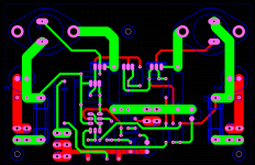
Looking at the gerbers with viewplot and everything is okay, except some of the drill holes arent present, on the polarized caps, some of the transistors and the big input film cap.
Whats up with that? and how do I fix it?
Note : Im using the standard libraries that comes with Eagle so that shouldnt be an issue.
Ran drillcfg.ulp, create excellon drill files from the .drl file with excellon.cam and then I created the gerber files with gerb274x.cam.
Attachments
Last edited:
Hi Neutrality,
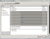
I use gerbv and I need to have the drill file at the top of the file list so it appears over the top of traces and pads. Still does not explain why some show and others don't.
If you want to email your pcb file I can have a closer look.
regards
I use gerbv and I need to have the drill file at the top of the file list so it appears over the top of traces and pads. Still does not explain why some show and others don't.
If you want to email your pcb file I can have a closer look.
regards
Attachments

Thats a serious bug and I thought Eagle was quite a mature package.
I would get in touch with them and see what they say, there might be a software patch out for it.
I would get in touch with them and see what they say, there might be a software patch out for it.
Thats a serious bug and I thought Eagle was quite a mature package.
I would get in touch with them and see what they say, there might be a software patch out for it.
What are you talking about?
What are you talking about?
The holes missing off his pcb ?
The holes missing off his pcb ?
I doubt the holes are actually missing in Eagle. Either the gerbers have not been created properly (extra layer included), the gerber viewer has an issue or maybe a minor operator error. The gerber viewer is not part of Eagle.
I have no problem with drills on eagle.
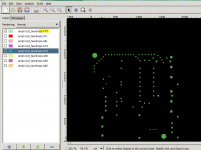
To see the drills corectly you will need the right file to be read by gerbv.
The file has extension *.txt , You can get 2 or more drill files as the manufactures needs.
Maybe you have to check again your cam generator settings.
To see the drills corectly you will need the right file to be read by gerbv.
The file has extension *.txt , You can get 2 or more drill files as the manufactures needs.
Maybe you have to check again your cam generator settings.
Attachments

Are the files standard excellon or extended excellon?
Extended excellon is similar to RS273X in that it will generate its own tool table, whereas standard excellon you have to create a drill table or it will ignore the holes. Extended excellon look similar to:
M48
METRIC,TZ
T01C.25
T02C.45
T03C1.4
T04C3.5
;LEADER: 12
;HEADER:
;CODE : ASCII
;FILE : 8000068B-1-8.drl for board 8000068B.brd ... layers TOP and BOTTOM
;T01 Holesize 1. = 0.250000 Tolerance = +0.000000/-0.000000 PLATED MM Quantity = 1026
;T02 Holesize 2. = 0.450000 Tolerance = +0.000000/-0.000000 PLATED MM Quantity = 143
%
G90
T01
X265000Y-52500
X475000Y-52500
X530000Y-52500
X575000Y-52500
Myself, I dont use Gerbers and Excellon any more as its old fashioned and can be a total pain, ODB++ is a much better format, less prone to errors and more manufacturer friendly. I dont know whether Eagle caters for this format, as I use Cadstar.
Like I said, I created a .drl file, made the Excellon file with that and then made the gerbers.
But some of the holes dont show, tried it a few times, same result. Weird.
Going to use makepcb.com, following their guide right here : http://makepcb.com/media/convert eagle files to gerber files.pdf
But some of the holes dont show, tried it a few times, same result. Weird.
Going to use makepcb.com, following their guide right here : http://makepcb.com/media/convert eagle files to gerber files.pdf
Last edited:
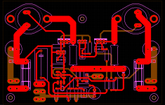
Well, found a cam file from sparkfun(sfe-gerb274x.cam) file that outputs :
* Top and bottom copper (.GTL, .GBL)
* Top and bottom solder mask (.GTS, .GBS)
* Top and bottom silkscreen (.GTO, .GBO)
* Drill file, 2.4 leading (.TXT)
It output a .dri file as well.
And it looks as it should, see attached image.
Would that be enough for most boardhouses or do they need more?
* Top and bottom copper (.GTL, .GBL)
* Top and bottom solder mask (.GTS, .GBS)
* Top and bottom silkscreen (.GTO, .GBO)
* Drill file, 2.4 leading (.TXT)
It output a .dri file as well.
And it looks as it should, see attached image.
Would that be enough for most boardhouses or do they need more?
Attachments
Last edited:
Those files that you show are ok.
You could see at iteadstudio or seedstudio.
Check the specifications of each boardhouse. Some times they need the files with other extensions or gerber format.
I tried this:
IteadStudio(more cheaper than ->),seedstudio.
You could see at iteadstudio or seedstudio.
Check the specifications of each boardhouse. Some times they need the files with other extensions or gerber format.
I tried this:
IteadStudio(more cheaper than ->),seedstudio.
Well, found a cam file from sparkfun(sfe-gerb274x.cam) file that outputs
Hi Neutrality,
I use a modified version of the sparkfun CAM file. I remember there was a layer missing, I think it was the component labels are missing. Anyway, worth double checking.
I have about half a dozen single-sided boards made using my modified CAM file and no problems so far. 😀
regards
- Status
- Not open for further replies.
- Home
- Design & Build
- Software Tools
- Eagle drill file error