Try this.
It's enough close to the real curves.
.subckt E55L p g k
;Rydel's Models Triode Mode
+params: gp=0.004735979219 b=3734.604234
+ c=0.3266713215 d=79.54627249
+ cgk=11p cgp=5p
+ cpk=1.8p mu=30
e1 1 0 value= {1+(v(g,k)/b)}
re1 1 0 100meg
e2 2 0 value= {v(p,k)/(v(p,k)+c)}
re2 2 0 100meg
e3 3 0 value= {v(g,k)+((v(p,k)+d)/mu)}
re3 3 0 100meg
g1 p k value= {gp*v(1)*v(2)*(pwr(v(3),1.5)+pwrs(v(3),1.5))}
rpk p k 100meg
c1 g k {cgk}
c2 g p {cgp}
c3 p k {cpk}
.ends
I built just such an amp, and it sounds fantastic. Real clean and simple.
However I have encountered reliability issues with these very expensive valves with quite a few simply flaming out after only a year or so of light use. As such I caution you about building this as a daily driver.
Shoog
Maybe the tubes are oscillating?
I had no indication that they were and had ferrite beads on all terminals. I think the reality is probably that running them as outputs stresses the very delicate grid wires.
Shoog
Shoog
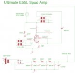
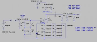
Here is my adjusted load line and schematic.
Curves traced with 2.5K LL, 170Va, 55mA.

Approximate schematic (doesn't fit real-world curves exactly). Cathode bias with the OPT primary returned to the cathode.

Think this is better, and easier. And will use ferrite beads, euro21 😉
Curves traced with 2.5K LL, 170Va, 55mA.
Approximate schematic (doesn't fit real-world curves exactly). Cathode bias with the OPT primary returned to the cathode.
Think this is better, and easier. And will use ferrite beads, euro21 😉
I think your CCS is overkill and any distortion it allows through will be miniscule compared to the OT. That level of impedance is appropriate for small signal valves.
Shoog
Shoog
This.
Especially considering that finding an appropriate size choke for this project is actually pretty easy.
On the other hand, CCSs are cheaper than a plate choke and they would eat enough of the ripple and noise from the PSU that you can probably get away with a single RC filter after the rectifier.
You just have to deal with the heat.
I am using a spare transformer for this project, 325VAC, a choke load is not practical with it.
I see the additional PSRR as only a benefit, which will reduce the number of components needed in the passive supply. The OPT will also have headphone output taps.
Other than the heat, which is accounted for, what is the downside?
I see the additional PSRR as only a benefit, which will reduce the number of components needed in the passive supply. The OPT will also have headphone output taps.
Other than the heat, which is accounted for, what is the downside?
IMHO the downside is the parafeed itself.
About a year ago I tried -as breadboard- the E55L parafeed layout, but it wasn't better (measurement), than OPT loaded E55L spud.
BTW the tried 1:1 -Slagle- interstage almost as costly than an OPT. :-(
About a year ago I tried -as breadboard- the E55L parafeed layout, but it wasn't better (measurement), than OPT loaded E55L spud.
BTW the tried 1:1 -Slagle- interstage almost as costly than an OPT. :-(
Attachments
An IXY by itself will have an order of magnitude higher impedance and lower parasitics than any OT so its impacts on the overall sound will be swamped. It can also cope withe the dissipation adequately if heatsinked. A stacked CCS is just overkill in every department.
Shoog
Shoog
I usually use cascode CCS as load, but serial connected capacitor and OPT primary, which is represent frequency dependent impedance (due to the loudspeaker and his crossover) always problematic.
do you you have any measures to show the issue? I like parafeed, its better than OTL to my ears. I understand the maths, but is it measurable?
This.
Can you connect L4 direct to V1?
Cheers, Mike
Yes, but I have been persuaded to go cathode bias by the folks who have chimed in due to propensity for thermal runaway and high grid current of these frame-grid pentodes. Updated schematic is in post #27, thanks for checking it out 🙂
An IXY by itself will have an order of magnitude higher impedance and lower parasitics than any OT so its impacts on the overall sound will be swamped. It can also cope withe the dissipation adequately if heatsinked. A stacked CCS is just overkill in every department.
Shoog
Well thanks Shoog, I'll take a look, do some simulations. I was more interested in the increased ripple rejection that could be attained in cascode and reducing the number of passive components in the supply, but perhaps it isn't necessary, will report back.
IMHO the downside is the parafeed itself.
About a year ago I tried -as breadboard- the E55L parafeed layout, but it wasn't better (measurement), than OPT loaded E55L spud.
BTW the tried 1:1 -Slagle- interstage almost as costly than an OPT. :-(
That is quite the diode string, euro21. In what way was the parafeed setup inferior? Very happy with my 45 parafeed SET. I know many do not like the reactive load, but substitutes high quality cap into the signal path as opposed to last PSU cap and simplified power supply with good PSRR. Bonus for me is I have a Sowter mains transformer appropriate for the project, with CCS load as opposed to choke.
- Home
- Amplifiers
- Tubes / Valves
- E55L Parafeed Spud Design - Your Thoughts