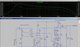
The E180F does not model as well as the EF86 did. The EF86 plots +/-0.1dB, the E180F plots +/- 2dB.
Attachments
Last edited:
Perhaps two things going on here. The feedback network is optimised for EF86? For a higher gain valve like E180F the 33M needs to be smaller, to remove the higher LF boost. Then the cathode decoupler needs to be bigger than 10uF to remove the lower LF droop.
There is not enough spare loop gain in a simple circuit like this to ignore valve gain when calculating RIAA components.
There is not enough spare loop gain in a simple circuit like this to ignore valve gain when calculating RIAA components.
I think a lot of the LF drop is from the iRIAA filter. If I remove it and look at the response, gain is only down 2dB at 20Hz compared to 100Hz.
I've added a zip with both the EF86 and E180F schematics as well as the .inc files for the tube models I'm using in case any one else wants to play with it.
The EF86 was +/- 0.6dB, not +/-0.1dB.
You will need to edit the spice include commands to point to the correct directory where you place the models.
Attachments
Last edited:
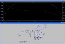
One thing that looks strange is a 4.7MEG load on the output.
I changed it to 47K
I moved the screen bypass cap to the cathode instead of ground
I increased R2 the screen resistor to 470K and changed R13 the cathode resistor to adjust the bias current and point
And I set C4 the cathode bypass cap to 100uf.
It looks much better at around +/-1dB and the LF looks better.
Attachments

The resistor at the output is not a load, but merely there to ensure 0V DC bias on the capacitor so a subsequent switch does not see jumps on changing source.
When there is plenty of loop gain, the two resistors in an RIAA network are usually 10:1 or 9:1 in value ratio. Anything much bigger than this means insufficient loop gain, which in turn means that frequency response will vary with valve characteristics.
When there is plenty of loop gain, the two resistors in an RIAA network are usually 10:1 or 9:1 in value ratio. Anything much bigger than this means insufficient loop gain, which in turn means that frequency response will vary with valve characteristics.
How much will the subsiquent load effect the frequency characteristics?
It seems to reason that with a pentode (even with feedback) it should have a significant effect.
It seems to reason that with a pentode (even with feedback) it should have a significant effect.
Hi Gimp,
I can't quite read the values in your inverse RIAA network, but if the equivalent source impedance is not in the range of a typical phono cartridge (or lower) it is going to interact quite badly with the RIAA EQ across the amplifier stage.
Edit: I used image zoom and it seems that your values are reasonable, but scaling them as I suggested still seems worth while.. As expected it does seem to show that cartridge source impedance is going to be important and interactions between the cartridge and EQ unpredictable on an individual basis.
The 47K resistor you have on the output should really be 4.7M as in the original design, and this circuit will be quite sensitive to output loading. (470K would be about the minimum IMHO, and higher would still be better.)
I was about to agree, but then I thought about it. Surely the inverse RIAA should be followed by a buffer, so it becomes a pure voltage source? If the preamp develops the correct RIAA response when fed from a voltage source, and has the correct 47k input impedance, then it is a matter for the cartridge manufacturer to ensure that his device works OK into this. Actually I can't see the point of using an inverse network in simulation- much better to take the actual response then compare it with a calculation.
The fact that the cartridge impedance is part of the feedback network in this type of design is actually a red herring. If the correct voltage is developed at the input point then in either this circuit or a more conventional one the outcome is the same. In either case the cartridge sees 47k as its load.
The fact that the cartridge impedance is part of the feedback network in this type of design is actually a red herring. If the correct voltage is developed at the input point then in either this circuit or a more conventional one the outcome is the same. In either case the cartridge sees 47k as its load.
<snip>
Actually I can't see the point of using an inverse network in simulation- much better to take the actual response then compare it with a calculation.
The fact that the cartridge impedance is part of the feedback network in this type of design is actually a red herring. If the correct voltage is developed at the input point then in either this circuit or a more conventional one the outcome is the same. In either case the cartridge sees 47k as its load.
I agree, I have gotten quite used to working directly with the RIAA response curve and can tell quickly if it is off..
Cartridge source impedance is not constant with frequency, nor is the inverse RIAA network used in these simulations, so interaction is likely..(This inverse network is not buffered in the simulation.) Some high output MC types which have both low inductance and resistance might work well with such a phono stage. The inverse RIAA network probably does not model the source impedance vs frequency of a real world cartridge either.
Interaction, yes, but it does not matter! (In the case of a real cartridge) Consider a cartridge as consisting of a voltage generator Vc with a source impedance Z(f). RIAA network has impedance ZR(f). Then output from this type of circuit (assuming infinite loop gain) is -Vc*ZR(f)/(Z(f)+47k).Cartridge source impedance is not constant with frequency, nor is the inverse RIAA network used in these simulations, so interaction is likely.
Now consider a more conventional circuit, with separation between source impedance and RIAA network. Voltage at input point is Vc*47k/(Z(f)+47k). A subsequent RIAA stage with a resistive input (say, 10k) will then give -(Vc*47k/(Z(f)+47k))*(ZR(f)/10k). Apart from a constant factor of 4.7 the two formulas are identical, so identical frequency response. The disturbance in frequency response caused by the cartridge impedance is the same in both cases, and the manufacturer will have ensured that the Vc*47k/(Z(f)+47k) is flat.
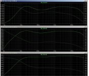
This is the same circuit with the load resistor for 4700K, 470K, and 47K.
The load has a significant effect on the frequency response of the circuit due to loading of the anode. If you don't accuratly load the circuit it won't behave the way the model indicates it will.
The load has a significant effect on the frequency response of the circuit due to loading of the anode. If you don't accuratly load the circuit it won't behave the way the model indicates it will.
Attachments
Interaction, yes, but it does not matter! (In the case of a real cartridge) Consider a cartridge as consisting of a voltage generator Vc with a source impedance Z(f). RIAA network has impedance ZR(f). Then output from this type of circuit (assuming infinite loop gain) is -Vc*ZR(f)/(Z(f)+47k).
Now consider a more conventional circuit, with separation between source impedance and RIAA network. Voltage at input point is Vc*47k/(Z(f)+47k). A subsequent RIAA stage with a resistive input (say, 10k) will then give -(Vc*47k/(Z(f)+47k))*(ZR(f)/10k). Apart from a constant factor of 4.7 the two formulas are identical, so identical frequency response. The disturbance in frequency response caused by the cartridge impedance is the same in both cases, and the manufacturer will have ensured that the Vc*47k/(Z(f)+47k) is flat.
I agree.. The effect should be the same in either case, wasn't thinking clearly about it..
First off, thanks guys for having a good look at this.
I was planning on using the preamp for various sources, Is this design specifically for RIAA stages or could I use it for CD as well?
Could some explain to me how I should measure the resistance from the source (CD player) output and the input on the power amp (Pete Millett’s DCPP)?
Sorry for the school boy questions
6J9P is supposed to be the same as an E180F. I've got both so I guess I have another project to add to my list.
😱
😱
Cool Gimp
Tried to add you EF86 and E180F spice files to lib. No joy
Can you tell me which sub folder they should be in? I only just downloaded Spice so steeeeep learning curve!
Cheers
Tried to add you EF86 and E180F spice files to lib. No joy
Can you tell me which sub folder they should be in? I only just downloaded Spice so steeeeep learning curve!
Cheers
..../if You told for 6Ж9П - 6J9P/, but the sound is not the same.....very far......😀....I tried 3 pairs 6J9P and 6J11P and...😱6J9P is supposed to be the same as an E180F. I've got both so I guess I have another project to add to my list.
😱
Very close to E180F is E186F! /I used first for 2A3RCA and second for JJ 300B!/
Last edited:
Can you tell me which sub folder they should be in?
.../lib/sub
Place here someone.txt .
Place Spice directive in shematic: .INC someone.txt
Yes, that is because the pentode has a high anode impedance and the circuit has insufficient loop gain for the LF end. The compensation for this in the RIAA network will only be correct for one value of valve gain e.g. one value of load impedance.TheGimp said:The load has a significant effect on the frequency response of the circuit due to loading of the anode.
I think you mean source and load impedance, not plain resistance. You can measure with a set of resistors and an audio millivoltmeter. Often easier to estimate it by looking at the circuit diagram. This preamp is for moving magnet RIAA only. Usually no need for a preamp with CD, but if you did need one this is not it. For CD you need low gain (or even less!) and a flat response. Some people like to add a little distortion and noise too, so it sounds more like LP.Dagwood said:Could some explain to me how I should measure the resistance from the source (CD player) output and the input on the power amp (Pete Millett’s DCPP)?
- Home
- Amplifiers
- Tubes / Valves
- E180F Preamp