As usual, interesting circuits You post 🙂 Only thing that let me perplex is the circa 2mA current trough the second ECC83, isn't a bit hot for that tube? But I suppose Philips know what their were doing, moreover in a pro amp...look at this one Philips HF309 Mono End Amplifier
Power consuption 85mA HT and 1,8A heater pro amp.
Mona
I think you should go fot 40% taps. And forget the bias board, you need
a matched quad of EL84 anyway. Also use a common cathode resistor
exactly as ST35.
Thanks Peter.
I did buy a "Matched Quad" of EL84s although I am just not sure how much I can trust things. I believe the vendor to be reputable, the tubes are modern Tung Sols and I have no reason to doubt they are "Matched" but would the bias circuit not be a good idea anyway just for piece of mind?
There's no performance penalty for using individual cathode resistors. Bypass capacitors should generally be much larger than antique designs, maybe 1000uF each. Capacitors are no longer expensive parts.
You also might consider adding a Zobel network across the output, maybe 0.1uF in series with 10R, 1W. Years from now, when you're rethinking this, you can add Zobels across the primary too.
All good fortune,
Chris
You also might consider adding a Zobel network across the output, maybe 0.1uF in series with 10R, 1W. Years from now, when you're rethinking this, you can add Zobels across the primary too.
All good fortune,
Chris
It is another item that can go wrong ( break or be mis-adjusted).Thanks Peter.
I did buy a "Matched Quad" of EL84s although I am just not sure how much I can trust things. I believe the vendor to be reputable, the tubes are modern Tung Sols and I have no reason to doubt they are "Matched" but would the bias circuit not be a good idea anyway just for piece of mind?
A common cathode resistor also helps the amp perform better, read about
d.gillespies paper about developing EFB where a common resistor was discussed.
See http://www.tronola.com/A_New_Look_At_An_Old_Friend.pdfIt is another item that can go wrong ( break or be mis-adjusted).
A common cathode resistor also helps the amp perform better, read about
d.gillespies paper about developing EFB where a common resistor was discussed.
for a description of common cathode resistor workings and the developing
of EFB.
We will forever disagree about this choice, because we have chosen different goals and have different expectations. Perhaps we could agree that for the highest possible performance and versatility, each output valve should have its individually adjustable grid bias voltage, and have its cathode connected to signal ground through a 10R or so resistor for current monitoring.
Adjustable "fixed" bias removes the cathode bypass capacitor time constant, gives complete independence of bias from other valves' current, and has the lowest distortion.
Historically this wasn't done for EL84 amplifiers because they were considered to be less than the best of the line. Today we can see them more clearly, as potentially brilliant, and give them the best possible supporting circuitry.
All good fortune,
Chris
It is another item that can go wrong ( break or be mis-adjusted).
A common cathode resistor also helps the amp perform better, read about
d.gillespies paper about developing EFB where a common resistor was discussed.
The EL84 amp that I custom designed years ago uses Gillespie's EFB system.
The difference with EFB over the usual cathode bias is amazing.
The amp's got more "punch", difficult to launch into distortion, and gains a few more watts.
What's better than that for an EL84 amp?
Of course, I'm using the Dynaco Z565's in it, I wanted the best iron.
Attachments
The voltage gain and phase splitter are of the same kind as the Philips HF309 with positive feedback.Only much higher resistances and a 100pF in parallel,you lose high frequence, probably compensated more or less by the feedback.
Fixed bias by elevating the cathodes, same thing as pulling down the control grids.Advantage, you don't need a negative supply.Drawback, you loose 12V of EL84 supply.
Mona
Fixed bias by elevating the cathodes, same thing as pulling down the control grids.Advantage, you don't need a negative supply.Drawback, you loose 12V of EL84 supply.
Mona
Last edited:

I aggree , this is a sensible compromise.The EL84 amp that I custom designed years ago uses Gillespie's EFB system.
The difference with EFB over the usual cathode bias is amazing.
The amp's got more "punch", difficult to launch into distortion, and gains a few more watts.
What's better than that for an EL84 amp?
Of course, I'm using the Dynaco Z565's in it, I wanted the best iron.
"what choice" ? It's unclear what this refers to. Please be more specific.We will forever disagree about this choice, because we have chosen different goals and have different expectations. Perhaps we could agree that for the highest possible performance and versatility, each output valve should have its individually adjustable grid bias voltage, and have its cathode connected to signal ground through a 10R or so resistor for current monitoring.
Adjustable "fixed" bias removes the cathode bypass capacitor time constant, gives complete independence of bias from other valves' current, and has the lowest distortion.
Historically this wasn't done for EL84 amplifiers because they were considered to be less than the best of the line. Today we can see them more clearly, as potentially brilliant, and give them the best possible supporting circuitry.
All good fortune,
Chris
Using tubes with similar characteristics is always better then trying to
adjust bias and Gm for dissimilar tubes ( if that is the choice). Using
identical tubes removed the need for adjustments of the above.
..... <snip> ....
I don't like the ST35, bad phase splitter and common cathode resistor 🙁
Better idea, look at this one Philips HF309 Mono End Amplifier
Power consuption 85mA HT and 1,8A heater pro amp.
Mona
Hello Mona,
I usually learn from your posts, but this one has me puzzled. Why don’t you like the ST35? Why is it’s phase splitter bad? Why is the Philips HF309 circuit better? Looking forward to your explanation. Is the explanation in your post #28?
Last edited:
Post #28 deals with the circuit of Wiseoldtech.Hello Mona,
I usually learn from your posts, but this one has me puzzled. Why don’t you like the ST35? Why is it’s phase splitter bad? Why is the Philips HF309 circuit better? Looking forward to your explanation. Is the explanation in your post #28?
The phase splitter of the ST35 is made with a inverting stage that would have a gain of -1x. The real gain is dependent of the resistors 2x270k (if my memory surves me right) and 47k and the open gain of the tube.That gain
is variable (depends on the state of the tube) and 2x the same resistor is only correct if the open gain is infinite.
And i don't like a common cathode resistor for the output.If one tube draws more current it steels it from the other, becomes hotter - steels more and becomes even hotter.
With each tube it's cathode resistor a current change automatically adjusts the bias voltage in the opposite direction.
And yes it demands bigger decoupling capacitors, no big deal these days.
Mona
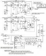
Schematic of the TS post #1
Mona
Yes, I supposed You were refering to that one.
"what choice" ? It's unclear what this refers to. Please be more specific.
Using tubes with similar characteristics is always better then trying to
adjust bias and Gm for dissimilar tubes ( if that is the choice). Using
identical tubes removed the need for adjustments of the above.
Valves are never exactly the same, and idling current changes with line voltage and aging. Maintaining balanced currents in the OPT primaries is essential for lowest distortion. Of course the more similar the valves are, the better the results.
All good fortune,
Chris
Any advantages to bolstering the power supply capacitance when you introduce EFB or are we splitting hairs talking about power supply sag in that bias arrangement? Minor dB improvements but nothing audible?
As it stands the C8B - 40uf cap will need to be a 47uf anyway but what of a 100uf?
As it stands the C8B - 40uf cap will need to be a 47uf anyway but what of a 100uf?
Schematic of the TS post #1
Just for clarity, the Dyna ST35 is a 7247 driver with split-load inverter and a tiny amount of positive feedback to the first stage cathode. Their schematic in post #1 is intended "to replace the transformer in commercial circuits".
I think we would agree that neither is optimal. But it was done half a century ago.
All good fortune,
Chris
Last edited:
Schematic of the TS post #1
Mona
Yeah sorry all I should have stated quite clearly that I have moved on from the schematic in the original post and have moved on to looking at a variant on the ST35 with EFB and possibly a bolstered capacitor in the power supply.
I am in the process of drawing the entire schematic and will post it for clarity.
- Home
- Amplifiers
- Tubes / Valves
- Dynaco EL84 PP variant questions