Went out and bought a nice Irwin #4 step bit. Home Depot is open at 7am, so was able to run out and get it before going to work. I hope I can do a little more work on the amp this evening.
I find dreaming up the circuit and doing the wiring both are a lot of fun. I don't enjoy metalwork, and I find layout to be a real chore. Good implementation is not easy.
I find dreaming up the circuit and doing the wiring both are a lot of fun. I don't enjoy metalwork, and I find layout to be a real chore. Good implementation is not easy.
Last edited:
I find the Irwin HS steel bits too brittle and tending to shatter. The hardware store and I have had words about it, their excuse is "that is what comes when we order bits now, that is hanson". I miss the Hanson and Vermont American HS bits (before sale to c*****, the VM stuff now is soft ****). I'm buying my drill bits now from mcmaster.com, when I can wait. When I can't wait, I buy Irwin titanium coated bits. They are expensive for working soft steel but they do actually work, until you resharpen them. Then the titanium is gone and the tip is too soft. Actually the best source of bits is the flea market, they still have American made VM and Hanson HS bits from bankrupt hardware stores. Just never the size you need today.
I drill big holes in sheet metal like tube socket holes with a punch when I have it (greenlea 3/4 conduit punch for 7/8" dia tube sockets) or by drilling a lot of little holes (9/32") inside the marking and connecting the dots with a Stanley carbide hack saw bit (round). Big drills like 7/8" mangle the sheet metal when I use them. You have to have a vise screwed to a heavy bench or plank to hold the work still to do accurate work.
I drill big holes in sheet metal like tube socket holes with a punch when I have it (greenlea 3/4 conduit punch for 7/8" dia tube sockets) or by drilling a lot of little holes (9/32") inside the marking and connecting the dots with a Stanley carbide hack saw bit (round). Big drills like 7/8" mangle the sheet metal when I use them. You have to have a vise screwed to a heavy bench or plank to hold the work still to do accurate work.
Last edited:
Argh, and this thing was expensive.
Should I just return it, get my money back, and buy a similar bit at Harbor Freight for $13, instead of the nearly $40 I paid for this at Home Depot?
Should I just return it, get my money back, and buy a similar bit at Harbor Freight for $13, instead of the nearly $40 I paid for this at Home Depot?
I think I'll order a Greenlee 3/4" chassis hole punch, and another one in 1-1/8" for octal sockets. I'm sure there's a thread here to point me to a good source...
Stupid newbie question: I'm just curious about those diodes in the 2nd diff amp. Wouldn't they provide a half-wave rectified local feedback signal  from the cathodes back to the grids?
rongon, I think your step bit will be perfectly fine since you're working with aluminum.
..todd
from the cathodes back to the grids?rongon, I think your step bit will be perfectly fine since you're working with aluminum.
..todd
Last edited:
Just finished enlarging the tube socket holes with the step bit. What a horrible experience. The bit did the first hole well enough, but was dull after that. Just got worse and worse. That'll teach me. I found the best price I could on new Greenlee punches and bought 'em. There's no comparison. The punches make such nice holes, and it's not that difficult. That step bit is an abomination. Maybe they work well if you have a nice, heavy drill press.
Anyway, it's done. Now to the wiring (the fun part).
Anyway, it's done. Now to the wiring (the fun part).
Stupid newbie question: I'm just curious about those diodes in the 2nd diff amp. Wouldn't they provide a half-wave rectified local feedback signal
..tj
Those diodes are there to prevent the cathode voltage from getting too far away from the heater voltage. Once the tubes start drawing current, the diodes will be out of circuit.
I'm trying to apply the same trick I learned about here (which I haven't built yet):
http://www.diyaudio.com/forums/tubes-valves/72536-el84-amp-baby-huey-122.html#post2893706
Also, there are a couple of articles on this on John Broskie's Tube CAD Journal site, but it's not easy to find old articles there.
I wish I could explain what the little electrons are doing, but I'm afraid my understanding of this is pretty limited. I understand what it's supposed to do, buut I don't understand the mechanism by which this gets accomplished. Maybe somebody can explain it?
--
Glad your hole is done. The one electrician I knew who liked step bits used Greenlea brand. HD has Greenlea hole punches in the 1/2 and 3/4 conduit sizes. 3/4 conduit is 7/8. Greenlea and Ideal testers and Ideal crimp tools are a few of the actual good things they sell. I'm not strong enough in the arms to use step bits.
I won't pick up Harbor Freight stuff laying in the middle of the road, except to put it in the trash. One exception- the diamond dust hole grinder bit set was unique and pretty good. They have probably gotten the supplier to make it cheaper, since.
I won't pick up Harbor Freight stuff laying in the middle of the road, except to put it in the trash. One exception- the diamond dust hole grinder bit set was unique and pretty good. They have probably gotten the supplier to make it cheaper, since.
Last edited:
my harbor freight step drills are ok, although I don't drill anything but aluminum, and they only go up to 3/4". I recently bought a 1 1/2" step drill from Amazon for $13 that is working out fine so far. I also will only use them with a drill press or on a piece that is so big or clamped so well that it won't move, and be sure to use some lubricant.
I have a dumb question... Does anybody know what the max value of grid leak resistor for a 12AT7 is when used in a LTP phase splitter? I put 1M, with 1k grid stoppers. Do you think those values are too large?
(I'm going with unbalanced RCA inputs for now...)
Otherwise, I'm almost done!
--
(I'm going with unbalanced RCA inputs for now...)
Otherwise, I'm almost done!
--
It's alive!
OK, it's assembled and playing music. Phew!
Did someone say they were going to watch and maybe learn? Well, take it from me... Work in a bigger chassis than a ST70. What a royal pain this was! It's awfully crowded in there, especially with my 3D layered layout. Fortunately, it worked. The amp is very quiet, at least through my moderately sensitive speakers.
I had an oscillation problem, which I traced to the grid leak resistors at the input, which were 1M. I reduced them to 330k and that seemed to make the 12AT7's happier.
Then I took voltages. Things were not right. I got too high a plate voltage on the 12AT7's, and that really upset the 6GU7's (they are DC-coupled, after all). I got 140V on the 12AT7 plates, and one side of the 6GU7 was drawing only a couple of mA, while the other side had practically no bias (Vgk) on it and was drawing 15mA. Talk about an imbalance! It finally dawned on me that the current source in the 12AT7 tail was limiting at 6.5mA, not the 8mA I was thinking I'd get. Oops. Well, rather than re-do the CCS, I increased the value of the 12AT7 plate load resistors to 82k and decreased the B+ to the 12AT7 from the almost 420V I was getting down to the original goal of 400V. That put the 12AT7 plates at 120V, which allows the 6GU7's to settle into a good bias point.
I had to increase the value of the 6GU7 cathode resistor to 10k. I wasn't getting enough of a difference from grid to cathode. Now I'm getting 6.5mA per triode from the 6GU7's and a Vgk of -6V. That's a little less current draw than I was aiming for, but it's still a pretty good spot on the loadline.
The heaters weren't floated high enough for some reason (it was only +40V), so I changed the network to get them floating on +60V.
The output stage settled in with no problems. I'm using a 350R cathode resistor. With EL34's I get 36V at the cathodes, which is a little more than 50mA per EL34, just like stock. With 6L6GC's I get 42V at the cathode, or 60mA per tube. That's with a B+ supply of 460V, so the plate voltage is 415V, so each 6L6 is dissipating about 25W. Perfect!
Then I decided to apply global NFB, to see if I had the polarity reversed. Wired it in and sure enough, it howled. Opened it up again and swapped inputs to the output tubes.
So..... After all that, I finally got it playing music. It sounds nice, but I it's too late to give the amp a fair hearing.
I hope to rope a friend of mine into letting me use his test gear to get an idea of what this thing is really doing. Hopefully I'm getting 10 watts per channel rms with decent looking square waves, and with no oscillations.
I'm not 100% happy with the layout. The 12AT7 and 6GU7 are physically way too close to each other. I hope since I'm not using them near their max dissipation that they'll survive it. Time will tell.
I'll post pictures soon. Be warned... This thing is ugh-LEE! I'm hopeless at making things tidy. This is the third circuit that's been in there, and it's old and crusty for sure.
--
Schematic of (untested) working build
This is the schematic showing the measured voltages with 125VAC from the wall.
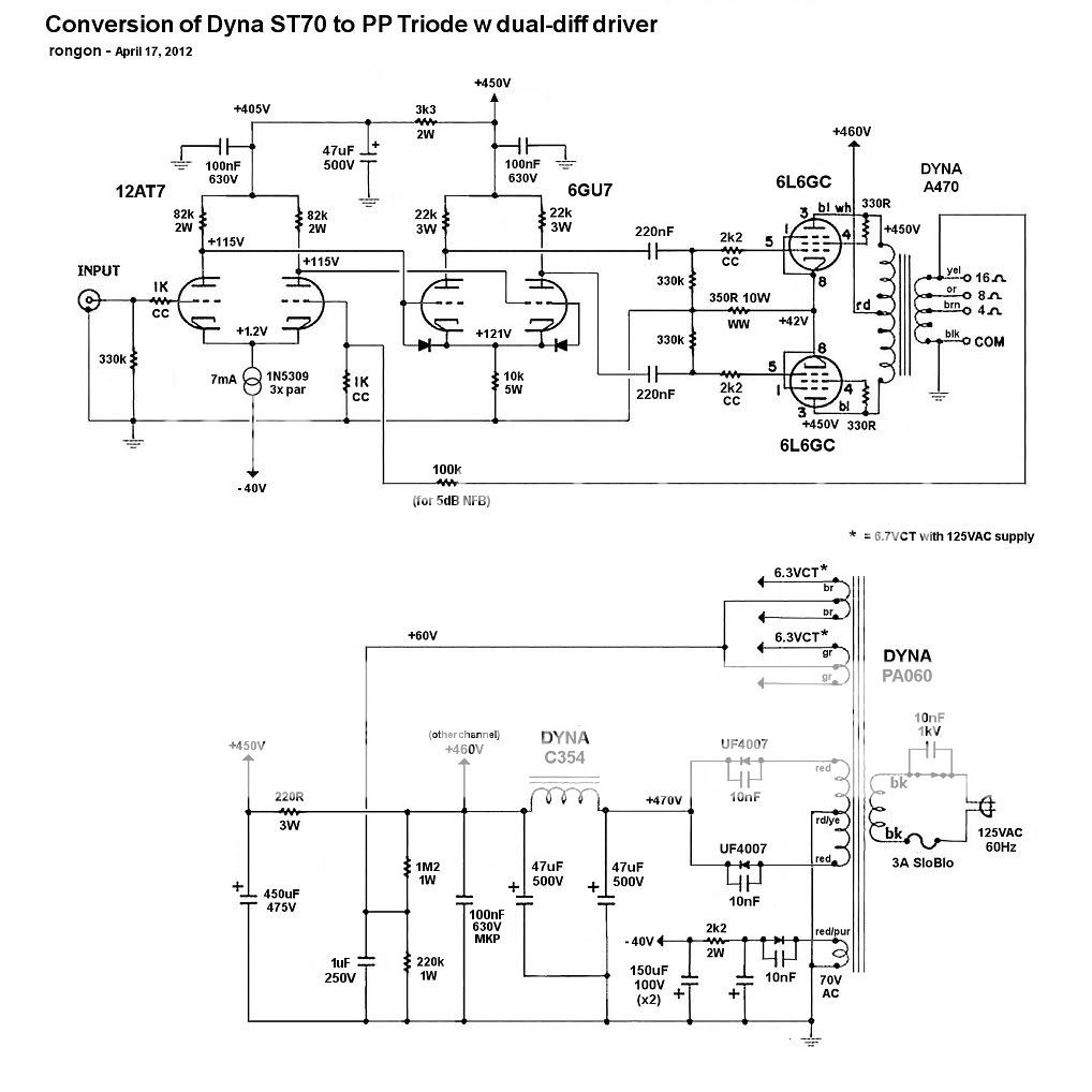
Some of the currents are a little different than I measured last night. Beats me why.
Each 12AT7 LTP draws 7mA (3.5mA per triode). Each 6GU7 push-pull driver draws about 12mA (6mA per triode). Both are drawing less current than I had hoped.
The 6GU7's should have at least a -5V bias (Vgk) to yield enough voltage swing for -6dB of gNFB. In other words, if I want to apply 6dB NFB around the amp, and the 6L6's have a grid bias of -42V, then each 6GU7 triode half needs to swing 84V peak. (Right?) I figure the 6GU7's are good for about 15X amplification, so that just makes it (6*15 = 90). I'll swap in some better-testing 6GU7's to see if I have weak ones in there. Or maybe I'll only be able to use 4 of 5dB of NFB.
Not shown are the 10nF 630V mylar caps from heater pins to ground (for RF bypass, hopefully following the method of M. Jones).
Does anyone see any horrible mistakes, or glaring weaknesses? Please bear in mind that there's practically no room left in this chassis. I'm planning on drilling some holes in the top plate for convection cooling.
--
Is there any advantage to putting grid stoppers on the 6GU7 grids? I've read that is not necessary when the two stages are DC-coupled, as they are here.
This is the schematic showing the measured voltages with 125VAC from the wall.
Some of the currents are a little different than I measured last night. Beats me why.
Each 12AT7 LTP draws 7mA (3.5mA per triode). Each 6GU7 push-pull driver draws about 12mA (6mA per triode). Both are drawing less current than I had hoped.
The 6GU7's should have at least a -5V bias (Vgk) to yield enough voltage swing for -6dB of gNFB. In other words, if I want to apply 6dB NFB around the amp, and the 6L6's have a grid bias of -42V, then each 6GU7 triode half needs to swing 84V peak. (Right?) I figure the 6GU7's are good for about 15X amplification, so that just makes it (6*15 = 90). I'll swap in some better-testing 6GU7's to see if I have weak ones in there. Or maybe I'll only be able to use 4 of 5dB of NFB.
Not shown are the 10nF 630V mylar caps from heater pins to ground (for RF bypass, hopefully following the method of M. Jones).
Does anyone see any horrible mistakes, or glaring weaknesses? Please bear in mind that there's practically no room left in this chassis. I'm planning on drilling some holes in the top plate for convection cooling.
--
Is there any advantage to putting grid stoppers on the 6GU7 grids? I've read that is not necessary when the two stages are DC-coupled, as they are here.
Last edited:
In your post #1 you seem worried about heater capabilities.
Take a look at this
Dynaco Stereo 70 heater capabilities
This amplifier has a current draw of 8.7A on a stock transformer and has been running for years.
Take a look at this
Dynaco Stereo 70 heater capabilities
This amplifier has a current draw of 8.7A on a stock transformer and has been running for years.
Wow, what a checkout. So many issues resolved. Congratulations. I've got the ST70 can cap hole plugged with steel mesh, to let the hot air out. But I have the radial lead caps under the deck, instead of hookup for 4 driver tubes. I also put new plastic feet on it to hold it up off the floor, so the slots in the bottom actually let some air in. I salvaged them from a motor drive PCB.
When you've got a current source symbol in a construction schematic, does that mean you put a pot there and adjusted for that current? What is with the 1n5300? Is that the base to resistor current source from the transistor cookbook?
When you've got a current source symbol in a construction schematic, does that mean you put a pot there and adjusted for that current? What is with the 1n5300? Is that the base to resistor current source from the transistor cookbook?
Last edited:
I think your heater supply is drawn incorrectly. You have it biased at +60v, but also show it tied to the HV center tap, which is at ground. I suspect it is not tied to the HV CT.
I think your heater supply is drawn incorrectly. You have it biased at +60v, but also show it tied to the HV center tap, which is at ground. I suspect it is not tied to the HV CT.
Absolutely correct. My bad. The LT supply center tap is floating on the voltage divider, NOT connected to the HT center tap. Thanks, I'll correct that and re-post the schematic.
--
In your post #1 you seem worried about heater capabilities.
Take a look at this
Dynaco Stereo 70 heater capabilities
This amplifier has a current draw of 8.7A on a stock transformer and has been running for years.
Ah, just what I wanted to hear! Thanks for the link to this. I was wondering if I could get away with 6550A's in there. I think I'll try that.
The question is... If I only draw 5.4A total from the heater windings, does that mean I can draw a bit more from the HT windings? I'm thinking the amp would sound better and be easier to drive with the output tubes drawing a hefty 70mA each. That would be a total draw on the HT supply of 280mA from the output tubes + 42mA from the driver tubes for over 320mA total. Can the PA060 hack that?
--
I'm taking it to a friend's shop for some 'scope-jockeying. I hope to see no awful oscillations, and get decent bandwidth at reasonable output power. A quick audition yesterday evening makes me think I'm getting a solid 10 watts per side. It sounded really lively and dynamic. We'll see what the signal generator and 'scope sayeth...
Last edited:
When you've got a current source symbol in a construction schematic, does that mean you put a pot there and adjusted for that current? What is with the 1n5300? Is that the base to resistor current source from the transistor cookbook?
I used three paralleled 1N5309 current regulator diodes ("CRD") per side. I only used them because they're tiny and I had some. They're nominally rated for 3mA each, but experience has led me to expect them to be far off their rating. In this case, each CRD is probably limiting to about 2.3mA, so I got only 7mA limiting per side, rather than the rated 9mA. That puts the plate current through each 12AT7 half at about 3.5mA. Close enough for me.
Thanks. Didn't know you could buy such things as current regulator diodes with a 1N number. Newark always has proprietary numbers for CRD's at a lot of money:I have never bought one. But then, for car battery charger currents, (which is what I was building) maybe that is why they are expensive.I used three paralleled 1N5309 current regulator diodes ("CRD") per side. I only used them because they're tiny and I had some. .
- Status
- Not open for further replies.
- Home
- Amplifiers
- Tubes / Valves
- Dyna ST70 to Dual-differential EL34 triode amp project