

I wish I could find the same skp files you found to make these beautiful picturesOh well any way I was messing around with Google Sketch and I have this images I hope you guys like them 🙂 the last image is where I got the idea
Regards
Juan
Hi Guys,
Thanks so much for taking interest in my troubles.
Apnneto,
Yes I saw that. I checked for continuity and it is good. It is from replacing parts and over heating while trying to remove solder. Hopefully I will not have to disturb that again. If so I will add a wire.
Earthquake,
I will sit down today and mark up a schematic. I can only get it to about 15V rails before R4 gets too hot. R4 and R35 are both dissipating a lot of current.
Andrew, That is a shadow. The only resistor that has smoked so far is R4. It still reads ok because I caught it in time. I will replace it when I have the issue settled.
Thanks guys!
Video about R4 and R35
Here you have an idea.
About increase of current resistors burning - YouTube
regards,
Carlos
Here you have an idea.
About increase of current resistors burning - YouTube
regards,
Carlos
Keep the good spirit and calm down dear Terry
We can be searching, everyday, till we find
You will listen this kind of quality:
MY DIY STEREO, DX BLAME ST, AIKIDO - YouTube
regards,
Carlos
We can be searching, everyday, till we find
You will listen this kind of quality:
MY DIY STEREO, DX BLAME ST, AIKIDO - YouTube
regards,
Carlos
Hi Caros,
I watched your video. The transistor you pointed out is the one I suspect. It is one ofthe BC556 transistors that I suspect is fake. They look like Phillips units with the silver face and they test OK on my meter but I suspect they break down under load. I have ordered some new ones from Mouser so I can replace them. I am building a SKA GB150 and used those same transistors and it is going high current as well. I should just leave both of them alone until I can replace those transistors so I don't burn something.
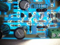
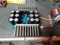
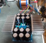
I did have one success today. I got the power supply finished. I tested it with a 150W light bulb and a 40-0-40VAC transformer. It will produce 55.7Vdc with no load and with the 150W light hooked across the + and - rails it drops to +/-52.5Vdc pulling 1.085A. I adjusted it down to +/-40Vdc to check the heatsinks. Current dropped to 9.75A. I let it burn for about 40 minutes and the heat sinks warm up pretty good but I can leave my hand on them right next to the devices with no problem so I believe they are ample.
Here's some pics.
I watched your video. The transistor you pointed out is the one I suspect. It is one ofthe BC556 transistors that I suspect is fake. They look like Phillips units with the silver face and they test OK on my meter but I suspect they break down under load. I have ordered some new ones from Mouser so I can replace them. I am building a SKA GB150 and used those same transistors and it is going high current as well. I should just leave both of them alone until I can replace those transistors so I don't burn something.
I did have one success today. I got the power supply finished. I tested it with a 150W light bulb and a 40-0-40VAC transformer. It will produce 55.7Vdc with no load and with the 150W light hooked across the + and - rails it drops to +/-52.5Vdc pulling 1.085A. I adjusted it down to +/-40Vdc to check the heatsinks. Current dropped to 9.75A. I let it burn for about 40 minutes and the heat sinks warm up pretty good but I can leave my hand on them right next to the devices with no problem so I believe they are ample.
Here's some pics.
Attachments
Look nice yes !
WOW mister Terry way to go !! I have goosebumps yes man way to go !!! this is fantastic ! I'm really happy that you got the Dx Regulator working 😀 you surely make my day thanks to show it that wow !
Regards
Juan
Hi Caros,
I watched your video. The transistor you pointed out is the one I suspect. It is one ofthe BC556 transistors that I suspect is fake. They look like Phillips units with the silver face and they test OK on my meter but I suspect they break down under load. I have ordered some new ones from Mouser so I can replace them. I am building a SKA GB150 and used those same transistors and it is going high current as well. I should just leave both of them alone until I can replace those transistors so I don't burn something.
I did have one success today. I got the power supply finished. I tested it with a 150W light bulb and a 40-0-40VAC transformer. It will produce 55.7Vdc with no load and with the 150W light hooked across the + and - rails it drops to +/-52.5Vdc pulling 1.085A. I adjusted it down to +/-40Vdc to check the heatsinks. Current dropped to 9.75A. I let it burn for about 40 minutes and the heat sinks warm up pretty good but I can leave my hand on them right next to the devices with no problem so I believe they are ample.
Here's some pics.
WOW mister Terry way to go !! I have goosebumps yes man way to go !!! this is fantastic ! I'm really happy that you got the Dx Regulator working 😀 you surely make my day thanks to show it that wow !
Regards
Juan
Now I know how Carlos feels when he see a success man it feels great wow I don't know how to describe this happy moment I have goosebumps wow 🙂
Regards
Juan
Regards
Juan
Hi Juan,
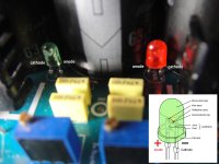
Thanks! I did want to point something out. The silk screen for the LED's on the positive rail is backwards. The LED's all have to point the same way. I found out the hard way. The LED's didn't light on the + side. When I checked the polarity I found it.
Blessings, Terry
Thanks! I did want to point something out. The silk screen for the LED's on the positive rail is backwards. The LED's all have to point the same way. I found out the hard way. The LED's didn't light on the + side. When I checked the polarity I found it.
Blessings, Terry
Good Terry...i am glad you did it.
That BC556 you can substitute or replace with any PNP available that has the same pin configuration.
Current there is not the problem..and voltage is also low.
There you do not need to have the same transistor.... this stage, the CCS, does not sound...ANY transistor will fit.
regards,
Carlos
That BC556 you can substitute or replace with any PNP available that has the same pin configuration.
Current there is not the problem..and voltage is also low.
There you do not need to have the same transistor.... this stage, the CCS, does not sound...ANY transistor will fit.
regards,
Carlos
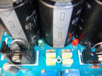
The same thing happen to me don't worried jejejejeje also that happens in the prototype so I decide to place the cathode upward on the positive rail see image attached 🙂 the red LED is hard to see the cathode but you can compare the green LED
Regards
Juan
Regards
Juan
Attachments
Last edited:
That BC556 you can substitute or replace with any PNP available that has the same pin configuration.
Current there is not the problem..and voltage is also low.
There you do not need to have the same transistor.... this stage, the CCS, does not sound...ANY transistor will fit.
regards,
Carlos
Hi Carlos,
That is good to know. I have to wait for the new ones to arrive anyway so I may as well just replace it at that time anyway. I'm very hopeful that this solves the problem. I can't think of what else it might be. I have been over and over the boards. None of the transistors measure a short. It must just go weird when it gets power.
Hi Juan,
I just wanted to post it to save others from having to unsolder those two.
I'm looking forward to using it when I get my amp boards working. 😀
Check with multimeter, using continuity buzzer, if not already made
for shorts in between transistor solders spots..... sometimes we have shorts there, hard to see without magnification.... check there..all transistors, in special the small ones and the BD ones.
It happens.... this happens....we look and it is fine...then we measure and the buzzer comes on.
regards,
Carlos
This is for you guys
I do not have a good heat sink yet but I want my motivate mister Terry I put together this channel to show you mister Terry I hope this give you a lift of motivation 😀
Sorry my Sony camera ca not record low frequencies that well
Dx Super A testing board for my friends - YouTube
Regards
Juan
I do not have a good heat sink yet but I want my motivate mister Terry I put together this channel to show you mister Terry I hope this give you a lift of motivation 😀
Sorry my Sony camera ca not record low frequencies that well
Dx Super A testing board for my friends - YouTube
Regards
Juan
Still4,
have you measured the installed Vbe of the suspect transistors?
V from b to e is +ve for an NPN and
V from b to e is -ve for a PNP.
have you measured the installed Vbe of the suspect transistors?
V from b to e is +ve for an NPN and
V from b to e is -ve for a PNP.
Mongo thanks for the Video. I like to see how everyone assembles their amp. Nice work! Keep on Rockin.......

- Status
- Not open for further replies.
- Home
- Group Buys
- Dx Super A and Dx Regulator Group Buy Interest