No problem at all... I really understand your position on this. I myself didn't pay much attention to specs and data until recently and always tried to build things and decide for myself if it was worth it or not. But since I cannot afford to build several concepts, I really have to analyze my options... I really don't care that much about design specs (THD, TID and so on), but it's nice to have some figures🙂 My goal is to find a topology that packs some power but also has great sonic quality. In fact, quality is my main concern here... That is way I ended up here... I have to say that I was impressed by your design and the positive feedback you received... That is why I asked you for some technical details, some measurement... and so on. But it's ok... I guess I'll have to simulate (some more) your design just to get a clue (I don't rely very much on simulations, I use them just to get started)... I do have some background in electronics, but my experience in building amplifiers is somehow limited (I've only built around 7 of them - none ended up in fire 🙂 ). I really appreciate your feedback... Keep up the good work!
I see... well, you are invited to simulate and to post your conclusions
Will be interesting, once more, to see the correlation....or no correlation, about sonics and measurements.
Will give me a help... this way, if you has confidence in your skills operating simulators ( I am not confident about myself with this tool)...if you have a good simulator...maybe you will produce something will be atractive to persons alike you, that has not time to try several amplifiers and go searching the track of quality evaluating numbers.
This way, next time, i will have something to offer to every folk that comes to this thread.
I will be happy to see.... make the most detailed test you can, and invited to post them here..... well... if you want, of course.
I think someone has made some testings... and published in this same thread or into the Dx amplifier thread (the big one)... or even into the group buy thread from Nordic... all i can remember is the guy has found a peak into 40 hertz... and that measured well... without any shame on numbers (because the result do not drives me happy or sad ... i just do not mind about) ..but i really cannot remember when, or were, was posted... from time to time someone wants those numbers.
You know.... i am the one search for results, not details..but i understand you cannot assemble to evaluate and because of that need numbers to understand how good some unit can be.. will not tell you...but i respect your approach.
I am the one searching for "effects"... results... if i was a Vulcano, i would not bother if my stones are sent 20 km distant or 22 km distant...i want to burn and to explode and spit smoke and stones...if the stones are rounded, if goes 20 kilometers, if the stone temperature when goes to land is 100 celsius or 300 celsius do not matters to me.
All i can say is the amplifier sounds good, measurements can result good or bad, and the amplifier will continue sounding good.
I think the DHR is even better in sonics...will measure, for sure, worse than this one....but sounds great ... and believe or not, distorts a little bit more than this one (have not rail regulators, more powerfull)
Thanks
Carlos
"...if i was a Vulcano, i would not bother if my stones are sent 20 km distant or 22 km distant...i want to burn and to explode and spit smoke and stones..."
Lol
great style, champ!
best wishes,
brian
Lol
great style, champ!
best wishes,
brian
precision 1 problem
Produce your tests again with higher voltage and them start your evaluation/debugging
Carlos
hi DX
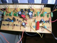
i tested the pr 1 with 45-0-45 and the only problem i could find was the B-E volts of bc547 and c4793 which were 128mv and 1.8v ????? respectively. I couldn't find the cause.
here's the pic...
Aman_4g@yahoo.com
Produce your tests again with higher voltage and them start your evaluation/debugging
Carlos
hi DX
i tested the pr 1 with 45-0-45 and the only problem i could find was the B-E volts of bc547 and c4793 which were 128mv and 1.8v ????? respectively. I couldn't find the cause.
here's the pic...
Aman_4g@yahoo.com
Attachments
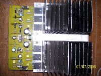

which one........? bc547 or c4793
it must be bc547 i think....
then what may be the cause of 100mv across Re and heating of the output trannies.
when i tested it with a 40watt bulb in series with the primary of the power transformer the bulb was glowing happily.......means theres some problem somewhere...
help me.....
thanks,aman
it must be bc547 i think....
then what may be the cause of 100mv across Re and heating of the output trannies.
when i tested it with a 40watt bulb in series with the primary of the power transformer the bulb was glowing happily.......means theres some problem somewhere...
help me.....
thanks,aman
Attachments
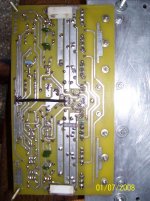
check for continuity from top (heatsink side ) pin of bc547 to the top leg of the 1k6 resistor in the row below it, I can't see the little wire link on your board, that is supposed to sit between Q7 and Q9, but it could just be from the low res photo... if it shows continuity, measure the voltage... carlos has the sims, so he would need that to help you when he comes online...
Errors.... none magical formula... not possible from brasil to inspect the board in
your place.... your eyes and hands will be needed to inspect carefully each connection you have made... for shorts, errors in leads position and so on.
Check the current into the output... measure voltage over power emitter resistances and inform us... milivolts over the emitter resistances.
Maybe you are having oscilations...because this voltage you are measuring from Base to emitter is not normal, off course... voltage there must be around 600 milivolts... from 500 milivolts to 670 milivolts... so... this measurement may be oscilations... check the feedback condenser if it is in place.. the small one connected to the feedback transistor base... also the Miller condenser, the compensation one you have into the colector of the Voltage amplifier stage... increase them and be sure you are using correct value (6.8pf can be readed, by mistake, as beeing 68pf for instance...of course other values and be readed wrongly too)
The voltage to the BC547 (protective device) shows the current is correct into the VAS...so....you may have errors into the differential or into the capacitors that may create oscilations... and this makes the multimeter goes crazy and read those voltages...maybe you have AC voltage into the output..this means oscilations... wrong capacitors, wrong values, non connected in circuit, missed.... check the zobel resistance and capacitor..if hot...means oscilations... then check capacitors missed, wrong positioned, bad soldered, wrong values.... oscilations normally has connections to capacitors and shows AC voltage into the output, also use to overheat the 10 ohms resistance into the zobel and also increase the output current a lot... the amplifier goes amplificating the oscilation, the high frequency..so...it goes working full power withou any audible sound.... increase the capacitor you have into the VAS..from VAS colector to the first fast transistor (the small one) base.... install 150pf minimum there for debugging purposes.
Well man.... amplifier works fine..... a lot of guys have built and works really fine without problems.... of course there are errors, burned parts, missed parts, wrong parts, inverted parts or something alike ONLY you can SEE those things into your board... now it is time to hard work...no magical formulas possible...hard work!.. inspection.... labour.... time and activity, ... inspection...measurements... checking capacitors, transistors and resistances.
We are here to help...but no magical mistery power to tell you, exactly, where there are wrong things made.... you have to find them.
This BC547 is there for protection purposes...it stays almost all the time off....not conducting from colector to emitter...low bias into this transistor... 100 milivolts (VBE) is not enougth to drive it to conduct...so it is "off"... when current is bigger, this current increases while the amplifier is operating and this drives this transistor "on"... and them it conducts from colector to emitter draining some signal to the negative line...this reduces the signal into the whole system and avoids too much current into the master VAS, the second transistor, the big one.
regards,
Carlos
prc 1 problem
hi DX
Thanks for replying and inspiring.......there must be problem somewhere but..........i ll dig it out and ll inform u as soon as possible.
regards Aman
hi DX
Thanks for replying and inspiring.......there must be problem somewhere but..........i ll dig it out and ll inform u as soon as possible.
regards Aman
Nice, the picture of you son
Well my dear friend...thanks to build the Precision I... i feel happy, glad and honored by your confidence and preference.
But, unfortunatelly, the more skilled we are more mistakes we make...and this happens because the self confidence... we think...we skilled and experienced folks into the soldering iron... that we have learned a lot... foolish... we are just humans... and the more proud more errors will be made... our vigilance, our attention, is reduced by our self confidence, our pride, and them we have worse results than a lot of beginners that can build that stuff slower but without mistakes... so afraigthned they are about those things, so unsafe they feel, they check many times and errors are smaller than we can make.
It is unavoidable...if you are good... skilled... experienced...will dig a lot.... will swet a lot holding soldering iron without believe you could made all that mess... and the wrong transistor will be facing you all time long... backwards...and we cannot see that.
Sorry.... bad luck to be good ..... sorry.
In this case...the good is bad
Carlos
My build of precision
Hi Destroyer!
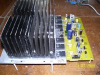
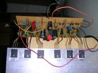
i Build one module of precision, and i run this with a 33vdc supply and
9400uf per rail. I get a typical sound of a dead transistor in output, but all the output transistor are fine, tested with dx amp too, the drivers and all transistor used in the amp works, pcb checked thousand times, build another pcb, all components new and the same sound. the only thing i not used is the fuses. i attached some pics.
I want to use it for a vocal monitor for me in my band.
any help is welcome!
Dá uma mãozinha de mestre pro brazuca aqui!!!
Thanks.
Hi Destroyer!
i Build one module of precision, and i run this with a 33vdc supply and
9400uf per rail. I get a typical sound of a dead transistor in output, but all the output transistor are fine, tested with dx amp too, the drivers and all transistor used in the amp works, pcb checked thousand times, build another pcb, all components new and the same sound. the only thing i not used is the fuses. i attached some pics.
I want to use it for a vocal monitor for me in my band.
any help is welcome!
Dá uma mãozinha de mestre pro brazuca aqui!!!
Thanks.
Attachments

Don't worry, about a thing, because every little thing... gonna be all rigth!
Human error my dear.
1) Check transistor for invertions
2) Check if PNP is really into the PNP side (negative side)
3) Check if NPN power units are into the correct side (positive side)
4) Check if you have not inverted the zener diode
5) Check all resistances...measure them, even into the circuit they must show a good reading..normally smaller than the correct value because of circuit resistances..having doubts, dessolder one side and measure with ohmeter.
6) Check each capacitor for correct value, and each electrolitic condenser for value, insulation and polarity
7) Measure your supply and be sure you have the correct positive and correct negative voltage.
8) Check all grounding points..be sure all grounds are joined together.
9) The input ground is to the input shield only...do not connect zobel ground, speaker ground or other into this input lifted ground..only, exclusive to the input cable shield.
10) Print your schematic and search for a red pen or pencil and paint each connection line, check them, each one of them, one by one and paint into the schematic till you have finish to paint all the stuff.
11) Check solder, must be brigth, do not shake soldering iron during soldering... the solder melted may move by itself, do not help and never spit or send breath of air, or air blow into the solder to remove heat...never do that!
12) Check lines for electrical continuity, use a buzzer or ohmeter into the lower resistance scale to check if you have interrupted copper lines.
13) Check each (each) paralell line to see if they touch one each other... clean board with Isopropilic Alcohol, or Kerozene, or Gasoline, or Paint Remover, use a brush and remove all flux (the brown dirty thing)...then observe things with a magnified glass or lenses.
14) If you're using VBE multiplier, check the transistor's position, and check if resistances and potentiomenter are connected correctly.
You have to remove your protective resistance to operate de amplifier, unless you will listen terrible distortions.... the resistance is there just to avoid too much big current if you have shorts into the board.... having a short circuit into the board, resistance will be very low... tenths of a ohm and all current will cross the board copper line... the resistance is there to limit this current to avoid fire and melted copper lines... also will protect transistors into overdrive as will limit currrent to a such ammount that will not be able to burn drivers and power transistors when wrongly assembled into the pcboard.
Measure the resistances from plus to minus, from plus to ground and from minus to ground... and them, invert your probe plug points and repeat those earlier three steps... resistances must be bigger than 20K in all cases... and not too much different from positive to ground compared to negative to ground (also when inverted)
The bias adjustment trimpot have to operate, tweaking it the current must change: increasing or decreasing...but must change, the trimpot must operate and the voltage drop over the protective resistances will change and the DC voltage measured there, as our spectations will change.
Off set must be small... less than 25 milivolts... the input must be shorted during off set and bias adjustment... AC voltage there, into the output, without signal entering (input shorted) means oscilations... AC voltage there, without audio entering the amplifier input is ZERO volts AC.... but some DC milivolts may remain there as usual.
Man, this is only hard work... to check all that stuff.... no spiritual help possible, also i cannot be over your shoulder and into your back (ahahahah) because our distance is too much big..from Northeast to Parana we have more than 3 thousand kilometers as minimum distance... so.... check for human errors... and you gonna find them..for sure, as usual, the way happens with all of us....normally, usually and daily.
Voltages from Base to Emitter, DC milivolts measured there, may be from 500 to 620 mV into all transistors... be carefull when doing those measurements... please, insulate your probe points with scotch tape, adhesive paper, plastic tubes or anything you have at hand to avoid touch coletor and base with your metalic probe points.... senão explode essa coisa toda!...... booooom!
A very good luck to you...meta bronca! (let's go ahead...move!)
Carlos
Attachments

yeah man, hard work! But I will try everything you have mention!
I used the same transistors of the schematic, they are not inverted, placed just right the layout. the resistances and caps all tested. I used a poliester cap 4.7uf in the input.
it is a human error(my error), sure!! But i cant see uihaiuha!!
I bulid a dx with 1 pair output and work very(VERY) well.
After i get sucess i will post the results here.
I appreciate your attention and time that you spend with me!
Thanks a lot!
I do not know about you, but i can observe an inverted transistor hours long
and still not realise it is inverted... there are something alike self convincement, self persuation, self pride, self confidence... all those things disturbs a lot.
First we think we have check and that everything is perfect.... secondly we do not check anymore... we decide that double check is fine... and there the error remains.
Happened so many times in my life that i do not believe in myself anymore and i use to check several times.... never believe in nothing, check by yourself, test by yourself.
You cannot see the mistake...but for sure it is there, as you have audio problems..so... not working properly is because there are errors....or... misadjustments.
Output transistors must conduct, so, 1 milivolt must be measured over the output emitter resistances.
Also, and very obviously, you may find more than 500 milivolts from base to emitter in ALL transistors.
Also you will measure voltage drop over the protective resistances, the ones you have in series with the supply rails... this voltage drop is not too much different when you compare positive rail and negative rail current... when off set is "under control" the current is not too much different... 10 miliamps more to positive rail.... this is the maximum allowable difference in current from positive rail to negative rail when compared.
Heat without signal entering means oscilations....or.... big error into the current adjustment, the stand by bias current, the iddle current is obtained dividing your voltage reading obtained directly over the protective resistances, a reading expressed in volts, by the resistance value to obtain the current expressed in Amperes.
Directly over the emitter resistance, i mean, one probe tip into one resistance extreme and the other one into the other lead.... measuring over.... the voltage developed into the resistance extremes that is the consequence of electrons flow.... some of them waiting to enter, and many of them into one side waiting into the line (strip) to enter and cross the resistance..so... you will have potential difference... electron potential difference.. electronic potential, wich is voltage.
Just to remember you.... a 600 milivolts reading , or 0.6 Volt reading divided by a 10 ohms resistance will result 0.06A.... or 60 miliamperes..... i knew someone that decided (wrongly) the voltage should be 6 volts... the one was adjusting to class A bias...very hot...ahahahahah... very hot.
Do not believe it is correct built... the signals (sintomas) shows it has errors... search for errors.
Humans do not make errors when they do not believe they made errors... this is the main error....not to believe they can make errors... a big mistake, a big error, to think this way.. the first and main error.
O fato de não acreditarmos na possibilidade de que cometemos erros faz com que não procuremos um erro que não cometemos.. se não procuramos um erro que cometemos, não achamos o danado do erro que fica lá na placa rindo da cara da gente.
The fact, the reality that we do not believe into the possibility we can make errors.. consists into the mains error... this produces as a result that we will not search for errors because we do not produce errors... we will not find an error that we do not believe it exists.. and them the damned still there laughing on us.
Agora tens que "ralar"... tens que "dar duro".... precisa trabalhar e pesquisar muito... vais achar... porque o êrro está lá esperando por você.
Now you have to work hard, have to seach and research a lot, you gonna find the problem, because it is there waiting for you.
regards,
Carlos
- Status
- Not open for further replies.
- Home
- Amplifiers
- Solid State
- Dx Precision, finally released... now debugged and better than HRII