@ metal: That's not correct.
Although most other european transistor markings like A,B,C tells you the breakdown voltage, it's different with BC54x. There, it's the hFe class. C is highest, while A is lowest.....
@Carlos, Nordic, (?) :
What do recommend for the lowest PSU voltage? I mean the voltage where DX precision remains it's performance without changing any other parts then the Zeners that original are 22V+33V? I guess that the VAS(Q10) will operate quite well with lower voltages since it has it's own current regulation (Q8).
Is that the same with the input stage? (OK, I see there is also a current regulator)
I do not need that high power (I will use the lower power rated 2SA1294/2SC3263 instead of 2SA1943/2SC5200) and I have quite a lot of +/- 35VAC rated at 500VA and only one +-45VAC reated at 400VAC transormers.
Thanks alot, Markus
Thanks metal. The Mouser BC547CG has a VCEO min (V) of 50. I had better compare that to a normal BC547, to be sure it is the correct one. Otherwise I could have problems similar to those of space2000.
billabong.
billabong.
Those should give you about 49VDC... so 2 22V zeners should do the trick... of course you can recalculate some of the resistors connecting to the power rails to keep the original currents there...
VAS is one thing I can only do with chips and valves, so we need to wait for uncle Charly to give feedback there... the CCS for the front end is regulated with its own 12V zener...
VAS is one thing I can only do with chips and valves, so we need to wait for uncle Charly to give feedback there... the CCS for the front end is regulated with its own 12V zener...
Seems you are correct weissi, as the Mouser BC547C has a hFE Min of 420, and Max of 800. so it really is the "C"version.
billabong.
billabong.
Thanks Nordic!
In the past 40min i was looking at the schematic and well, I guess Carlos' topology reacts quite relaxed on power supply fluctations, so *marginal* lower rail-voltages shouldn't hurt precision1's qualities.
Some sidenote to your boards:
I wonder why all those holes for the wire jumpers are drilled just with 0,8mm? I'd liked to use 1mm wire for all those GND jumpers.
Btw, what's the copper thickness? 35µmm or 70µmm? Some traces look very narrow (not from the functional point, just seen from the *kidding* "audiophile" point of view).
I've tried to shave off the solder-stop mask of and cover the traces with tin, but this looks so ugly, my method just disfigures those very nice boards 🙁
cheers
BC547C, or any transistor with selection "C" will be better to use than others
Input transistor operates with rail voltage only..... not rail to rail voltage... to the Precision, BC556 and BC546 are the transistors to be used, not BC547.
Into Precision i have not tested lowest possible voltage.... but it may work fine reducing to 35 volts if you want.
Some instabilities may happens if reduce under 25 volts.
The amplifier is for 64 volts..... to lower voltage you have nice HRII, beautifull Dx Standard and a lot of wonderfull others.
To operate very low voltage have to recalculate many things...you can do it if you want...i am not interested...Precision is ready to people build, and this is the news i am interested.
I am focused into Panzer (NAD)
regards,
Carlos
Thanks Carlos!
Since I plan to drive my speakers balanced (or bridge tied load, or differential, however this will be called, I guess you know what I mean...), I want to be on the save side of current demands for the transformator. Therefoe I think I will have more headroom with those +/- 50VDC transformators @ 500VA than with the one with +/-62VDC @300VA....
cheers,
Markus
The bigger voltage one seems that will produce short term burst very interesting
And those bursts of power are very nice.... maybe you are rigth about the 50 volts unit....well... i have tested that but was down the eigthties and do not remember anymore the results.
35 Volts DC i mean.... i have tested it using this voltage, so, i am sure works fine.... will have to change zeners and reduce output pairs.
People say experience has enormous value... i am starting to disagree.... i am starting to loose memory... so... old references are going by.... and those things are "experience"...
May be good till you have 50 years old..but more than that..hehehehehe...better the retirement.... i am 57 years old.... what was i talking about?
regards,
Carlos
Sorry Carlos, I've just edited my post, deleting that silly sentence about AC/DC (!). Of course you meant DC.
Well, Impedance curve of my Visaton TIW200 doesn't show ugly impedance minimums, but when I use 2 Precision boards into 8Ohm load where the woofer places a minimum of ~4Ohms, that would mean each amplifier sees 2 Ohms, so the transformer will be loaded quite heavy.
On the other side I have used the same speakers with single LM3886, also connected in balanced mode... and I have never recognized problems that the LM's where going into SPiKe protection.
Infact it was playing very well and if you ask me why I build another one, while the old was doing well... hmm, I think I'm addicted to electronics
Hi Wessi, yep, the holes on those pads are my only regret...
I simply didn't see that they were that small untill I had the boards in my hands...
On the other hand using a wire that will fit the holes will have more than enough current handleing ability, also the pads are quite big so it can be drilled out a little to accept a 1mm wire if you feel the need.
Current carrying trace widths have been caluclated and a little margin added, surface area was not in shortage so i didn't have the need to go to thicker than 35micron
The traces are covered in Sterling silver, if they tarnished a little in shipping, just give them a rub down with some Silvo, they should solder fine though at 350C.
Thanks Nordic!
I've already drilled them up to 1mm, no proplem with this. And I'm sure that also 0,8mm will be enough for this distance at the expected current. It just looks better to my eyes
Indeed I had faced problems to solder the boards, but shifting from 1mm to 0,5mm solder wire cured that. Maybe it's just the different flux thats inside the smaller solder.
Are this boards RoHS compliant?
Nevertheless I proceed finishing the boards and I'm sure these amplifiers will impress me. Finally i can seriously listen to something else than my headphones. I feel more comfortable in tweaking digital electronics like D/A's I just have way to much OS-CON's that I cannot use in high voltage amplifiers. someone needs 100uf/20V OS-CONs?
I've already drilled them up to 1mm, no proplem with this. And I'm sure that also 0,8mm will be enough for this distance at the expected current. It just looks better to my eyes
Indeed I had faced problems to solder the boards, but shifting from 1mm to 0,5mm solder wire cured that. Maybe it's just the different flux thats inside the smaller solder.
Are this boards RoHS compliant?
Nevertheless I proceed finishing the boards and I'm sure these amplifiers will impress me. Finally i can seriously listen to something else than my headphones. I feel more comfortable in tweaking digital electronics like D/A's
I just have way to much OS-CON's that I cannot use in high voltage amplifiers. someone needs 100uf/20V OS-CONs?update DX-prc I picture
hi,
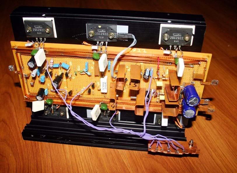
here i made a bit change on star ground and some others on my prcs-I amp. is this correct way to doing star ground? comments pls. it is about 3.5 inches far from the circuit. you can see the copper plate it is on top of the plastic base so there is no way to contact with the hsin.
thank you.
hi,
here i made a bit change on star ground and some others on my prcs-I amp. is this correct way to doing star ground? comments pls. it is about 3.5 inches far from the circuit. you can see the copper plate it is on top of the plastic base so there is no way to contact with the hsin.
thank you.
Hi space2000. Good to see someone building the Precision 1.
You were the first on this forum to build and have one working, and considering it was ALL diy, quite commendable. You are a very quick builder.
Thank you for posting your progress, because as a result we have discovered that Q7 should be changed to a BC546 or BC556.
Your new board looks ok to me ( though I'm not very qualified to comment).
The wires to the star point copper pad could be shorter. You may be able to place the star point under the board to overcome this. The copper pad star point should be a lot smaller too, I think. You could have a brass screw protruding from the pad through the board for external connections.
If this is still a test setup, then just try it as it is, and then make changes as needed.
Further comments may come from the more experienced.
Billabong
hi,
i found this way star ground giving me more clear, dinamic sound then it's place under the board. i tested both but this is the best way i found, sound very clean and sharp, very sweet too but bass a bit less then last time.
may be dx can tells me more about it....right, wait for him....
thank you..
I have found that soldering a tag onto each ground wire and then blting the group together give a very satisfactory star ground.
I have also found and others have confirmed that the order of placing the various grounds affects the technical performance of the amplifier.
Using a bolted connection through all the tags allows experimentation to improve a hum problem if it crops up.
I have also found and others have confirmed that the order of placing the various grounds affects the technical performance of the amplifier.
Using a bolted connection through all the tags allows experimentation to improve a hum problem if it crops up.
yes, i have made this way...make them a group and connect to gnd....all you see are each group of gnd....so i just keep out the main GND plate from the circuit.
I use a frame style ground ... around the board i have a surrounding ground bar
Inside that i use the positive line and the negative line.
This is what i use to my own things...home constructions... had never problems with that.... people has worries about...it seems to me the method i use works fine.
But there are other ideas about... i really cannot explain you as they are confused to me, and i really do not mind as my method have never created me problems...so.... it is already ready and done in my mind..nothing to worry about, i think.
Also i do not prepare boards to my amplifiers, i am not able to do..cooperators use to help me in such things...they are better to explain that stuff.... Nordic may be able to explain that star ground method better than i can.
regards,
Carlos
Attachments
Precision I- minor problem need to solve
Hi DX,
Regarding Precision-I:
I want to inform you that my amp is now much more clear and sharp then last time, sweet sound too but bass has drop lots. What can I do to have more deep bass?
The amp is working fine without any problem. Not getting much hot or any major problem occurring.
Thank you.
Michael
- Status
- Not open for further replies.
- Home
- Amplifiers
- Solid State
- Dx Precision, finally released... now debugged and better than HRII