Ryan, it is not that simple, but I have been useing that method with good enough results... as I said, just leave them in the meter for a minute or 2 to dissipate your added body heat...
I ted to handle them by attaching an adhesive lable (which is why I send out some sticky transistors - it avoids the heat transfer allowing faster testing)
P.S I need to e-mail you later, we seemed to have missed processing your and two other transactions... after enough days it basically times out, and the processing company can not do it anymore. Will send you some instructions of how to proceed a little later, just busy touching up a pcb before etching... the stupid lazer printer ate my sheet of press and peel so I settled for photoetching today...
Do not worry to match them...also relax about the condenser
the electrolitic condenser can be 16 volts.
The voltage there, under normal operation is very low....of course if you have damages you gonna have high voltage there and it will be under the risk to explode..... so... your choice to put 16 volts (my choice) or bigger voltage.... the best possible choice is something alike 64 volts, but the one will be enormous!... i prefer the risk, but this is up to you.
The matching of transistors produce lower off set and better audio quality.... the better the matching the better the results...but unmatched works fine too...the losses in quality will not be perceived as you had not listened the unit with matched ones...so...not having a reference you perceive absolutelly nothing.
Of course all transistors will operate better if matched, the amplifier had two rails, one take care of the positive going signals and the other the negative going..better if they have the same size when reproduced... differences cannot be a very good idea...but sounds good without matched ones too.... i do not use matched to my tests..so...if you use matched the sound will be better than the sound i have listened here...i use to make things to real world...and real world is a sligthly mismatch into transistors as people is not rich enougth (a lot of folks are not) to buy hundreds to select the matched ones.
Those transistors into the differential are sensitive to matching, and also this 1K5 or 1K6 resistance may need small tweaking...the idea is not to have too much VBE differences related the NPN versus the PNP..... the NPN use to work with lower VBE ...but the difference cannot be bigger than 25 percent.
The voltage regulators, series regulators, using series pass transistor and zener reference of voltage is the filter rails filter and stabilizers i am talking about...sorry if the name i use is so strange...yep.... those BD139, BD140, some zeners, and some capacitor.... and this is important, very important, also to check in advance your supply with a resistive load to see the real voltage loaded...and them to select your zeners in accordance to that.
Conecte uma carga na saída de sua fonte de alimentação, de maneira, de modo, que a corrente nominal para a carga que vais usar seja drenada... então meça e anote essa voltagem... escolha o zener de acordo para ter uma perda de 1 ou 2 volts com referencia esta voltagem lida sob, debaixo, condicciones de carga.
Connect a resistive load into your supply output..both rails having load same time...the nominal current must cross the resistance, the current your amplifier will use to work full power over your speaker (impedance).. and them measure, write this voltage in a piece of papper not to forget or save it into your multimeter into hold function...now select your zener to a voltage lower than that 1 volt or a little bit lower.... this way you will never have losses of voltage, will never drop....not having voltage variations into the input circuit you will have no risks to have the audio modulated by those variations..this means, dinamically pure, very pure audio..nothing added because the supply sags of voltage.
regards,
Carlos
Hi Carlos with the last error the most this cap saw was 40VDC, so I guess even 50V would be good enough for the paranoid..
Yes... when something wrong happens, transistor invertion, mistakes during the
construction, bad solder, cold solder joints, transistors wrong, NPN in the place of PNP, small pieces of solder creating shorts, resistors in wrong position, say, one in the place of other.... 220K in the place of 22 ohms or the opposite, broken copper lines because of transport or bad use.... inverted zenners, missed voltages, well.... almost all errors appear into the ouput with a very big off set...no more off set, sometimes you have rail into the output when you have not more than rail voltage there.... so... this will go to the feedback line and this voltage will appear into the feedback transistor input, into the differential pair... and this condenser is connected to this point to DC voltage and also to signal, so... big voltage can appear while you have damaged amplifier or not debugged (for errors) just assembled amplifier...so...in this case this condenser can burn as will face big voltage... solution is to put diodes in parallel to condenser, but this creates other worse problems..so...please...if you are afraid..put a bigger voltage condenser there.
When things are wrong... transistor burned, big voltage into the output...i think i will not be bothered if this condenser explode too..but people worried about that can put a 64 volts there...more safe of course....it is up to you.... you decide!
Mine is 16 volts and i am ready to accept the risks as my amplifier do not use to work damaged..and them voltage there is milivolts.
regards,
Carlos
Yes... when something wrong happens, transistor invertion, mistakes during the
construction, bad solder, cold solder joints, transistors wrong, NPN in the place of PNP, small pieces of solder creating shorts, resistors in wrong position, say, one in the place of other.... 220K in the place of 22 ohms or the opposite, broken copper lines because of transport or bad use.... inverted zenners, missed voltages, well.... almost all errors appear into the ouput with a very big off set...no more off set, sometimes you have rail into the output when you have not more than rail voltage there.... so... this will go to the feedback line and this voltage will appear into the feedback transistor input, into the differential pair... and this condenser is connected to this point to DC voltage and also to signal, so... big voltage can appear while you have damaged amplifier or not debugged (for errors) just assembled amplifier...so...in this case this condenser can burn as will face big voltage... solution is to put diodes in parallel to condenser, but this creates other worse problems..so...please...if you are afraid..put a bigger voltage condenser there.
When things are wrong... transistor burned, big voltage into the output...i think i will not be bothered if this condenser explode too..but people worried about that can put a 64 volts there...more safe of course....it is up to you.... you decide!
Current there will not be bigger than 5 miliamps to produce a explosion i think...but i may be wrong.
Mine is 16 volts and i am ready to accept the risks as my amplifier do not use to work damaged..and them voltage there is milivolts.
regards,
Carlos
Imagine you have rail voltage...and also imagine the condenser is
connected direct to the ground into the negative side....the positive side has 64 volts that crossed R3 (15K)... the one in series with the output line and the feedback transistor base...
Now lets imagine that invertions of voltage and excess of voltage will make the condenser zero ohms... a short inside the condenser.... well... 64 volts will cross 15000 ohms in advance to cross the condenser.... the current will be small, maybe 5 miliamps, as in this voltage divider, 15K and almost zero are in series with the ground...so...power there will be minimum, you can damage your condenser, but will not explode....knowing it is small, if you face problems, alike big voltages into the output (defects into your construction, errors, mistakes) then you have to replace this small and cheap condenser for safety purposes.
I prefer this way then to put a huge one there....your decision, up to you.
regards,
Carlos
Attachments

That about describes what I saw... even the resistor next to it goes brown, but does not catch fire...
Re: The reasons of this peak
I was pulling your leg about being "offended" by a peak of .003%. I'm from tube land and folk there are happy if they get peaks of "only" three orders of magnitude higher that .003%
Francois G said:
Hey Murry, I have to ask if you are joking about a 0.003% peak?
Cheers,
Francois
I was pulling your leg about being "offended" by a peak of .003%. I'm from tube land and folk there are happy if they get peaks of "only" three orders of magnitude higher that .003%
Ryan,
Matching HFE with a DMM is MUCH better than not matching at all. I use a pair of short, blunt needle-nose pliers to grab the transistors and insert them into the DMM. Works great, and NO heat instability. You could try different methods or instruments for grabbing and inserting the transistors. Use what you like best, just make sure your body heat doesn't go near the transistors.
..Todd
Ryan,
In the P1 you need only match the two Master devices in the LTP, the Slaves do not require matching for dc offset purposes. Like has been said, a DMM will work fine for these small signal devices and great advice on the heat transfer issue, the fingers will make HFE rise as it warms up so you will definately want to measure them at room temperature. Everyone has an opinion, but your DMM will do the job needed very well indeed, always works for me in a pinch.
Colin
Latest DX Precision I schematic attached.
Hi Colin,
When you say 'master' are you talking about the PNP transistors in the LTP? (Q1 & Q3?) I can't really figure out what the NPN transistors do; Do they boost the gain of the PNPs, or stabilize the current? or ??
Just curious, I'm try to learn.
..Todd
Hi Colin,
When you say 'master' are you talking about the PNP transistors in the LTP? (Q1 & Q3?) I can't really figure out what the NPN transistors do; Do they boost the gain of the PNPs, or stabilize the current? or ??
Just curious, I'm try to learn.
..Todd
Attachments
While I'm on the topic of dumb electronics questions, let me ask this...
The leftmost rail decoupling caps (in the Precision I schematic) are 220uF which, as I understand it, shunt any lingering AC to ground. And these are bypassed with 47nF which extends the frequency response of that shunt much higher, killing any high frequency noise. Have I got that right?
So how do we decide when to use 100nF (as is usual) or 47 nf? Is it just a choice of corner frequency?
..Todd
Many thanks by the new schematic.... very pretty as your usual work
You are very good with that stuff Todd.
Collin, my dear friend.... i am glad to have you around.... if you feel confortable to explain Todd go ahead.
Doctor Self book, page 83 and 84 explains how this work to reduce third harmonic... said linearise the circuit and halves third harmonic.... the book shows graphics and gives the name of the circuit... complementary Szilai pair or something ....
Do you have the book dear Todd?
I can have it and send it from brazil...hehehehe..will have to wait mail arrives.
regards,
Carlos
Hi Carlos,
I think I have every book about amplifiers, including Self's book, but they are hard to understand for me. It makes more sense every month that I read this forum and apply what I learn to real life circuits.
I'll go read those pages. Thanks.
..Todd
I think I have every book about amplifiers, including Self's book, but they are hard to understand for me. It makes more sense every month that I read this forum and apply what I learn to real life circuits.
I'll go read those pages. Thanks.
..Todd
Forum teaches us more.... i have learned a lot here,
and still learning.
Books texts are made to the people that already know...so, they know that they already know..the go satisfied without learn nothing, only an ego massage.
They learn that they know, almost the same as the book writer.
ahahahah.... book seems to work this way.
But sometimes, doubts and words.... i know what that circuit does to my ears.... but he called that "linear"..... i felt quality.... he called "halve the THD"...so.... helps a lot to communicate, as teach us words that everybody understand.
Now i can make advertising..the sound that i have appreciated is because THD is halved and the input circuit is more linear.
regards,
Carlos
Hi Todd,
Yes, q1+3 provide the voltage gain, and the npn's provide current gain and buffer the inputs of the ltp leading to much lower output impedence, along with the local feedback provided also dramatically helps to linearise the CFP ltp. This is a simple explanation and there are many others who can provide further detail, but the best explanation is that it just simply sounds good and very musical 🙂, but has a catch,VERY techy to get right and easy to make sound non musical also..
Colin
Are you ready?
have felt, at least once, the divine emotion in your heart?
have you perceived the God's presence and strength?
Do you feel emotions when US black people sings Gospel music into a church...have you cried once listening?
have danced listening?
So i will invite you to feel the emotion...join Dx Amplifier team man!... i ensure you that you gonna feel God!
And i am not a religious man...maybe the opposite, but this is the most Divine emotion i could ever feel... do you like HRII?......ahahahahahahhaah...sorry, nice toy!
Have a average quality speaker, those Sansui and the same average level stuff?
Have Pink Floyd music...of course the most famous album....
then turn your volume up with Precision, just to have 100 watts average only....let room to strong dinamic undistorted peaks.... and make a fast visit to the Paradise..... the visit is for fell seconds only.... long time presence is not allowed to us for a while.
Precision I (Roman letter ONE) is your ticked to Divine emotions
Feel the Divine emotion, built and listen a Precision!
You have never listened anything like that!
Put it loud...very loud and feel the emotion in your breast!
regards,
Carlos
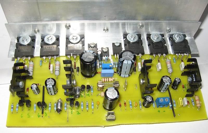
Nordic, I prefer employing OP transistors from the same maunufacturer and from the same run, in particular if the project is an audiophile amplifier.
In addition the aluminium transferring "L"-angle looks too thin. I'd rather use ~4mm grosness.
Otherwise the PCB design is excellent. Congratulations!
I hope the amplifier will perform good in the real life.
In addition the aluminium transferring "L"-angle looks too thin. I'd rather use ~4mm grosness.
Otherwise the PCB design is excellent. Congratulations!
I hope the amplifier will perform good in the real life.
- Status
- Not open for further replies.
- Home
- Amplifiers
- Solid State
- Dx Precision, finally released... now debugged and better than HRII