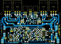
Just by adding pre driver Q17, Q18 MJE340 and MJE350 to AX-14P layout it will become AX-20P, schematic is almost identical minus pre driver.
AX-20 layout image for reference it has some mistakes IN4007 are reverse and base of Q17, Q18 are not connected.
Regards
Sonal Kunal
AX-20 layout image for reference it has some mistakes IN4007 are reverse and base of Q17, Q18 are not connected.
Regards
Sonal Kunal
Attachments
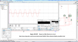
Ok Juan you can start the job now.🙂Hey thimios I'm back a placed the circuit on the simulation and yes it works but KTA1268 is not available on my simulation and I use 2SA954 instead also 2SD1857A is not on my simulation so I use BD139 I know this is only software simulation but at least it give an idea that the circuit works an it does work see images 🙂
I call this circuit " MONTARBO " is was name it on the image you send me 😛 let me know what is the real name later when you get a change man 🙂
Regards
Juan
Apex answer is that T3(Vbe multip.)isn't on main heatshink.
Ok Juan you can start the job now.🙂
Apex answer is that T3(Vbe multip.)isn't on main heatshink.
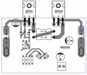
ok perfect then 🙂 I will continue here then I will try to make it as simple as possible here is the first image
Regards
Juan
Attachments
Just by adding pre driver Q17, Q18 MJE340 and MJE350 to AX-14P layout it will become AX-20P, schematic is almost identical minus pre driver.
AX-20 layout image for reference it has some mistakes IN4007 are reverse and base of Q17, Q18 are not connected.
Regards
Sonal Kunal
hello sir 🙂
as you can see I already begin the project but give me some time to make sure all is correct I'm also working with another project so as soon is done I will post the PDF files so you can etched unless you don't want to wait I can send you the Sprint Layout file so you can modified the way you want it that is another option if you wish 🙂
I made a simulation and all seems to work good to 8 ohms load and sine wave of 1KHz 700mVp it give about @8 ohms 193W and the THD is really low according to the software 0.002% t@ 4 ohms load same setting it can give about 387W and THD of 0.002% of course that with 65V rails and also will depend of the power supply too this is just a "approximation" with the software maybe the results in real time might be different 🙂
I think we should post this on the correct section of mister Miles so all information will be there for other to see #1
Regards
Juan
Attachments

Last edited:
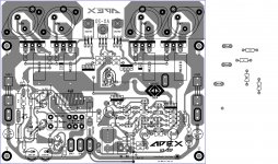
Here is the last image mister sonal kunal please check it and I will continue checking for errors or better say bugs just in case 🙂
Regards
Juan
Regards
Juan
Attachments
Here is the last image mister sonal kunal please check it and I will continue checking for errors or better say bugs just in case 🙂
Regards
Juan
sir juan, where the correct polarity C6: 100uf / 16v between # 141 and # 145.
thank you in advance
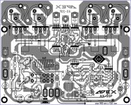
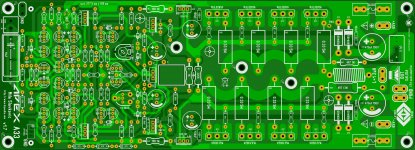
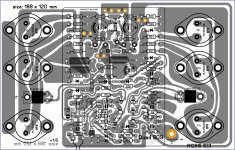
Hello guys I haven't post for a while here and I have a new layout that I still working on it and is the A33 from Apex this one is double layer and I spend a lot of time making connections and it was not easy at all, to be honest this is my first double layer PCB and I will keep checking for errors just in case 🙂
Regards
Juan
Regards
Juan
Attachments
Thanks for the excellent tutorials. Very useful.
This guy makes the most beautiful PCBs I ever saw -
http://www.nixieclock.org/?p=36
Chinese Nixie tube clock.GPS Adjust. PCB Art.
This guy makes the most beautiful PCBs I ever saw -
http://www.nixieclock.org/?p=36
Chinese Nixie tube clock.GPS Adjust. PCB Art.
Last edited:
Thanks for the excellent tutorials. Very useful.
This guy makes the most beautiful PCBs I ever saw -
????????(???I) ??QS30-1?????????????? Nixie Clock Home | ?????
Chinese Nixie tube clock.GPS Adjust. PCB Art.
wow that is what we call it art a master PCB I love it 🙂

Regards
Juan
Hello guys I have not post anything for a while so I found this Quad 909 layout here on diyaudio really cool layout here is the
link #15 Quad 909 Clone
where a member name Kei post the image and from there I almost can say I made a clone of the layout really not so accurate but I'm getting there 🙂
link #15 Quad 909 Clone
where a member name Kei post the image and from there I almost can say I made a clone of the layout really not so accurate but I'm getting there 🙂
Attachments
Nice work Juan. Glad you are still interested in Audio amplifiers.Hello guys I have not post anything for a while so I found this Quad 909 layout here on diyaudio really cool layout here is the
link #15 Quad 909 Clone
where a member name Kei post the image and from there I almost can say I made a clone of the layout really not so accurate but I'm getting there 🙂
- Status
- Not open for further replies.
- Home
- Amplifiers
- Solid State
- Dx Juan layouts ideas PCB