A small error remain in the pcboard layout... was not fixed by Juan
Zimmer informed the error remain there.
Please, do not assemble the last pcboard published in thread above till i post the fixed layout.
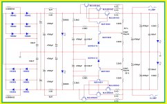
The schematic shows two output pair, in the reality we are using three, this is a matter to include on more only.
Soon we gonna have this fixed.
regards,
Carlos
Zimmer informed the error remain there.
Please, do not assemble the last pcboard published in thread above till i post the fixed layout.
The schematic shows two output pair, in the reality we are using three, this is a matter to include on more only.
Soon we gonna have this fixed.
regards,
Carlos
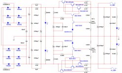
We are fixing the layout and also making an upgrade into the Dx Supply
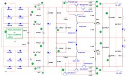
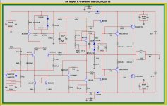
It was made to be used together the Dx Super A.... good to feed two channels pumping full power... reason why i have changed something in the schematic..include more capacitors and one transistor more.
Resistor of 0.000001 is the resistance of the cable.... do not worry...it is nothing.
Coils are two layers, each layer may have 12 to 15 turns, wire is 0.5 to 1 milimeter diameter... total turns from 24 to 30 turns... resistor will be the core, as 3.3 ohms resistor, a 5 watts unit.
regards,
Carlos
Attachments
Last edited:
We are working into the Dx Supply layout..nobody sleeping here
Working hard...without stop.
Juan is increasing high current tracks width.
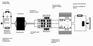
Here you have also an example of connections...observe fuses...each one of them must be calculated based into your parameters....if you are novice and wants some help.... a beginner...then come to uncle charlie and i gonna give you, gladly, a helping hand.
carlos.eugenio1951@yahoo.com
regards,
Carlos
Working hard...without stop.
Juan is increasing high current tracks width.
Here you have also an example of connections...observe fuses...each one of them must be calculated based into your parameters....if you are novice and wants some help.... a beginner...then come to uncle charlie and i gonna give you, gladly, a helping hand.
carlos.eugenio1951@yahoo.com
regards,
Carlos
Attachments

Last edited:
post723,Working hard...without stop.
Juan is increasing high current tracks width.
Here you have also an example of connections...observe fuses...each one of them must be calculated based into your parameters....if you are novice and wants some help.... a beginner...then come to uncle charlie and i gonna give you, gladly, a helping hand.
carlos.eugenio1951@yahoo.com
regards,
Carlos
the switch must go in the same Live feed as the fuse.
Here you have updated files about the Dx Supply
It is appointed to be used together the Dx Super A.... in a matter of fact, any series pass regulator will fit..the ones have error amplifier.
This one was hardly tested since they where published by Ampex in 1973...i have modified a little but it remains almost the same circuit.
Enjoy and be happy...here you have updated files about it.
Please, do not build before you have read all Dx Supply thread...if you need some help, then email me your parameters and i will give you some help about... Dx Supply thread is here
http://www.diyaudio.com/forums/powe...utput-adjustable-stabilized-power-supply.html
read it from the first to the last post to know the evolution and all details you must know to decide what to do further.
regards,
Carlos
Attachments
Sorry folks, but remain error in pcboard
Juan made a mistake again
Because of that he will assemble the next fixed circuit at home in advance to publish images or send em to me.
I am sorry.
Do not assemble the last posted images because has serious errors.
regards,
Carlos
Juan made a mistake again
Because of that he will assemble the next fixed circuit at home in advance to publish images or send em to me.
I am sorry.
Do not assemble the last posted images because has serious errors.
regards,
Carlos
Juan made a mistake again
Because of that he will assemble the next fixed circuit at home in advance to publish images or send em to me.
I am sorry.
Do not assemble the last posted images because has serious errors.
regards,
Carlos
thank you for your information uncle charlie, but which one of the last posted image were mistake, i mean from what page / post.
No image is good...first because we made update... we have made a new
and better, and stronger supply.... all images posted after that...with the new supply, had mistakes.
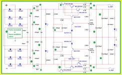
So, you can trust in the last schematic posted (green and yellow frame surrounding it) but you should not trust in any layout published.
This forum does not allow us to delete posted images...better would be if we could delete the wrong ones..but i cannot..so..they are still there, posted and wrong.
Do not assemble based in ANY layout made to the Dx Supply.
One that i have made by hand you can trust..but that one is the first model that is too much weak and cannot face the drain of current of two channels operating full power at 2 ohms loads.
Answer is "no one!".... no layout is really fine.
Wait the Zimmer layout or Juan Vargas layout tested with photograph of prototype assembled and tested shown as certificate and guarantee of quality and reliability.
regards
Carlos
and better, and stronger supply.... all images posted after that...with the new supply, had mistakes.
So, you can trust in the last schematic posted (green and yellow frame surrounding it) but you should not trust in any layout published.
This forum does not allow us to delete posted images...better would be if we could delete the wrong ones..but i cannot..so..they are still there, posted and wrong.
Do not assemble based in ANY layout made to the Dx Supply.
One that i have made by hand you can trust..but that one is the first model that is too much weak and cannot face the drain of current of two channels operating full power at 2 ohms loads.
Answer is "no one!".... no layout is really fine.
Wait the Zimmer layout or Juan Vargas layout tested with photograph of prototype assembled and tested shown as certificate and guarantee of quality and reliability.
regards
Carlos
Here you have the schematic
If you can, then make your own layout or wait our future fixed (real fixed) layout that gonna be posted together picture to show you it was tested.
regards,
Carlos
If you can, then make your own layout or wait our future fixed (real fixed) layout that gonna be posted together picture to show you it was tested.
regards,
Carlos
Attachments
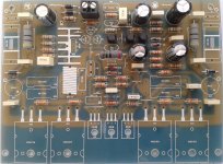
We are testing the Brazilian layout.
Here you can see.
It is the Dx Blame ST pcboard modified to receive the Super A circuit.
This layout was made by Zimmer..he said this is mainly to Brazilians..but if the devil pay he can ship to the hell.
For a while we have not ordered production...we are testing...soldering and dessoldering to see copper track resistance to solder and dissolder and testing watching the scope and some torture tests too.
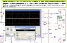
Brazilians wants to use other transistors....i am preparing a video showing the limits of each one of these transistors easily available in Brazil....they want SO3 too....watch the TIP35 limits, as an example.
regards,
Carlos
Here you can see.
It is the Dx Blame ST pcboard modified to receive the Super A circuit.
This layout was made by Zimmer..he said this is mainly to Brazilians..but if the devil pay he can ship to the hell.
For a while we have not ordered production...we are testing...soldering and dessoldering to see copper track resistance to solder and dissolder and testing watching the scope and some torture tests too.
Brazilians wants to use other transistors....i am preparing a video showing the limits of each one of these transistors easily available in Brazil....they want SO3 too....watch the TIP35 limits, as an example.
regards,
Carlos
Attachments

Last edited:
Clever idea! having the board to accommodate TO-3 transistors or TO−3PBL ones, I like it!
Regards
Juan
Regards
Juan
There's a small pulse during power on..when we switch the amplifier on
http://www.youtube.com/watch?v=V161Tk4ev-Y
Milisecond pulse at 0.58V RMS of amplitude
If you do not want it, then reduce C7 (Zimmer schematic 2 posts back) to 47uf.
Juan pcboard is C37... from 220uf to 47uf
regards,
Carlos
http://www.youtube.com/watch?v=V161Tk4ev-Y
Milisecond pulse at 0.58V RMS of amplitude
If you do not want it, then reduce C7 (Zimmer schematic 2 posts back) to 47uf.
Juan pcboard is C37... from 220uf to 47uf
regards,
Carlos
Last edited:
Hello Sir
greetings in post #731 have you stimulated the circuit in multisim looking for spice
models of MJE15032 MJE15033 PLEASE can you share these models if its possible
warm regards
andrew lebon
greetings in post #731 have you stimulated the circuit in multisim looking for spice
models of MJE15032 MJE15033 PLEASE can you share these models if its possible
warm regards
andrew lebon
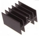
Here is another photo.
I still have to buy the rest of the components to solder them, heatsink has to be cut from the middle too.
Zimmer, your PCB is looking nice, good work too.
Carlos, are friends planning to do regulator PCBs 🙄
I also ordered some heatsinks for this PCB, fits exactly like the one Juan uses.
I still have to buy the rest of the components to solder them, heatsink has to be cut from the middle too.
Zimmer, your PCB is looking nice, good work too.
Carlos, are friends planning to do regulator PCBs 🙄
I also ordered some heatsinks for this PCB, fits exactly like the one Juan uses.
Attachments
Last edited:
😀 oh metal that build looks really good!!!! make me reallly happy forgot to add that  muy bien !!!!!
Regards
Juan
muy bien !!!!!Regards
Juan
Last edited:
I have these transistors in my Multisim 12, but i do not know how
to collect this data to you...sorry Andrew.
Metal.... very good..... very nice.... we will make the pcboard...Juan is doing it, but will take some time as he is on vacations for a few weeks...he will make and the same blue colour of you pcboard...already half made.
Also Zimmer is making the pcboard also, but his pcboards gonna be white, and this is different from your pcboard colour.... of course you can have it..but you may not like the colour difference...then..better to go to Juan Vargas.
Here you have a video about what happens along the first miliseconds after you switch power on..the off set variation, the power on thump or power on tip (in our case)... in English and Portuguese:
Dx Super A - what happens during miliseconds power on - YouTube
If you want protection here is the link:
DX Blame Amplifiers - Carlos Mergulhão
The one undestand how the circuit works is the responsible, Miguel Nabuco, or Mitchel in our forum and his email adress is the one below:
miguelnabuco@terra.com.br
regards,
Carlos
I have to wait for 3~4 weeks for these small heatsinks to arrive, so delay is not a big problem, what really matters is producing the same PCB quality for this regulator. Juan work was very good such that he correctly measured components leads diameters, it was a real bonus for me because once I inserted the component, I did not have to hold it back into PCB when I soldered its leads because drill sizes are very accurate.
I am still seeking for a reliable source of MJL4281/4302, if any body knows where I can get them original and cheap, please let me know.
I am still seeking for a reliable source of MJL4281/4302, if any body knows where I can get them original and cheap, please let me know.
- Home
- Amplifiers
- Solid State
- Dx Blame ST together Dx Super A