I found threat too much long... .confused....i was searching for the old layout and i found difficult, reason why i am collecting here something about.
Dx Blame was in the early beginning called Dx Blame ES (means YES)...because was a copy...or almost a copy...or deeply inspired into Doctor Self design called Blameless.... so, this is Blame YES because i had the blame to copy.
Dx Blame ES is the one sounds the best..but it is in the limit into the VAS and sometimes a transistor goes!...the BC546, first VAS sometimes melts...was replaced by 2N5551 and became better....but even this way was attacked by some guys that feel it imprecise.
Yep...really was my mistake...but i have insisted...i keep the circuit because the sound was unbeatable....and even now a days i am having doubts if the ones i made after, the more modern ones, are much better...there are some details in the sonics the Blame ES is spectacular....for instance..two voices..talking two different languages at same time...mixed....it is easier to undertand both singers, or both speakers, or both guys talking, if you are using the ES.....it means to me it is because of harmonics...very low harmonics not messing with the original sound.
The Blame ES was killed...i have replaced by the Dx Blame ST to have a more stable amplifier being offered and to shut off some mouthes that were mining the courage of some guys to assemble.....this resulted fine as hundreds have built, in special in Brazil
Todd Johnson was not happy...also Metal not happy...also Rudi not happy.... people was not happy with mine decision...but i do not regret..no way to keep an amplifier when people came in groups to attack and to say it had flaws...and it had flaws.....so.... the new model was to fix...i tried to fix changing a little....i found sound good...but some magic was lot there...reason why in my home i am using the original ES schematic and when i inject some high level pulse..sometimes the BC546 goes...... two times in three years...i do think this is something i can face.
The defect that is bringing a nice effect...something interesting.... was partially or totally fixed in the ST, i am not sure as i am not using it
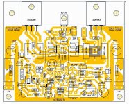
I found in google the layout made for a Brazilian group inside a Brazilian forum...where two batches were distributed...almost 200 kits including power supply, speaker protector and surge protector...no more pcboards available folks....this is not an advertisement.... i will collect some informations and post it here, as soon i found them all, to allow people to build at home.
We have also, a third group, the blue pcboards (not available too) could accept four different models and in this site you have all informations:
Amplificadores DX Blame - Carlos Mergulhão
Just as an starting point, here you have the layout .... one of them..not the Todd Johnson one, nor the Metal one...this one was made by Miguel Nabuco, in Brazil, based and authorized by Todd Johnson.
Because i had troubles to find the stuff...this is the reason why i am opening this thread.
The subject was the thread "I am trying to develop a new amplifier, the Dx Blame ES...." ..... inside this same thread we turn into the Dx Blame ST.... and then a big ammount of time as i was out from the forum focusing into the Brazilian forum, helping people to build the green pcboards from the brazilian group... then a group buy for the blue boards was opened...and the blue boards had the option, as you can see, to build the Dx Blame ES and also the Dx Blame ST....it is just to use the correct parts referenced by a chart.
Slowly, as i am searching material, i will post all needed stuff here to make easy to the ones wants to build the amplifier.
What i was perceived, and this is important,...better sound is achieved while using BC546/556 and also while using BD139/140
regards,
Carlos
regards,
Carlos
Dx Blame was in the early beginning called Dx Blame ES (means YES)...because was a copy...or almost a copy...or deeply inspired into Doctor Self design called Blameless.... so, this is Blame YES because i had the blame to copy.
Dx Blame ES is the one sounds the best..but it is in the limit into the VAS and sometimes a transistor goes!...the BC546, first VAS sometimes melts...was replaced by 2N5551 and became better....but even this way was attacked by some guys that feel it imprecise.
Yep...really was my mistake...but i have insisted...i keep the circuit because the sound was unbeatable....and even now a days i am having doubts if the ones i made after, the more modern ones, are much better...there are some details in the sonics the Blame ES is spectacular....for instance..two voices..talking two different languages at same time...mixed....it is easier to undertand both singers, or both speakers, or both guys talking, if you are using the ES.....it means to me it is because of harmonics...very low harmonics not messing with the original sound.
The Blame ES was killed...i have replaced by the Dx Blame ST to have a more stable amplifier being offered and to shut off some mouthes that were mining the courage of some guys to assemble.....this resulted fine as hundreds have built, in special in Brazil
Todd Johnson was not happy...also Metal not happy...also Rudi not happy.... people was not happy with mine decision...but i do not regret..no way to keep an amplifier when people came in groups to attack and to say it had flaws...and it had flaws.....so.... the new model was to fix...i tried to fix changing a little....i found sound good...but some magic was lot there...reason why in my home i am using the original ES schematic and when i inject some high level pulse..sometimes the BC546 goes...... two times in three years...i do think this is something i can face.
The defect that is bringing a nice effect...something interesting.... was partially or totally fixed in the ST, i am not sure as i am not using it
I found in google the layout made for a Brazilian group inside a Brazilian forum...where two batches were distributed...almost 200 kits including power supply, speaker protector and surge protector...no more pcboards available folks....this is not an advertisement.... i will collect some informations and post it here, as soon i found them all, to allow people to build at home.
We have also, a third group, the blue pcboards (not available too) could accept four different models and in this site you have all informations:
Amplificadores DX Blame - Carlos Mergulhão
Just as an starting point, here you have the layout .... one of them..not the Todd Johnson one, nor the Metal one...this one was made by Miguel Nabuco, in Brazil, based and authorized by Todd Johnson.
Because i had troubles to find the stuff...this is the reason why i am opening this thread.
The subject was the thread "I am trying to develop a new amplifier, the Dx Blame ES...." ..... inside this same thread we turn into the Dx Blame ST.... and then a big ammount of time as i was out from the forum focusing into the Brazilian forum, helping people to build the green pcboards from the brazilian group... then a group buy for the blue boards was opened...and the blue boards had the option, as you can see, to build the Dx Blame ES and also the Dx Blame ST....it is just to use the correct parts referenced by a chart.
Slowly, as i am searching material, i will post all needed stuff here to make easy to the ones wants to build the amplifier.
What i was perceived, and this is important,...better sound is achieved while using BC546/556 and also while using BD139/140
regards,
Carlos
regards,
Carlos
Attachments
I will colect all material i have to post
Because i found hard to find the stuff...so.... the only text was the introduction and then i gonna post Brazilian boards..and then all i have from Todd Johnson (my Dx Avatar in this forum show his layout) and from others too.
regards,
Carlos
Because i found hard to find the stuff...so.... the only text was the introduction and then i gonna post Brazilian boards..and then all i have from Todd Johnson (my Dx Avatar in this forum show his layout) and from others too.
regards,
Carlos
Great Cantunes..... i am glad to see you around
Thank you.
Mitchel (Miguel Nabuco) sent me the files.
So, here you have all about the Brazilian pcboards...called Green boards.
Now i gonna be searching for Todd Johnson original, also something from Metal too (red pcboards)
To let, registered, as a memory and as a source of information, to forum folks.
regards,
Carlos
Attachments
Thank you Cantunes...i am searching for the files about it
Power supply, how to adjust, the star ground..... then i gonna post it here.
To be something people can find what they want and fast...i will avoid comments...to make the thread small.
Thanks a lot dear Cantunes.
I will post pictures too... on that subject you can help a lot.
Mete foto amigo!..... insert images dear friend!
regards,
Carlos
Thank you Cantunes.
Here you have Greg Erskine site that has also the Dx Blame ST... it is a little bit different because not the Brazilian version, but it is the international version.
Greg's Web Site
regards,
Carlos
Here you have Greg Erskine site that has also the Dx Blame ST... it is a little bit different because not the Brazilian version, but it is the international version.
Greg's Web Site
regards,
Carlos
Here you have it playing bass
regards,
Carlos
Dx Blame ST as subwoofer amp. -17+17V supplies - chapter 1 - YouTube
regards,
Carlos
Dx Blame ST as subwoofer amp. -17+17V supplies - chapter 1 - YouTube
Hi Cantunes , how many uH for the inductor in the psu cicuit .
thanks
Not a critical value to the inductor.
Put few turns, wire from 0.5 to 1 milimeter diameter , from 8 to 15 turns depending the size of inner resistor.
regards,
Carlos
Put few turns, wire from 0.5 to 1 milimeter diameter , from 8 to 15 turns depending the size of inner resistor.
regards,
Carlos
Yes.... Andrew is rigth.... try air core and remove the inner resistor
I found this a flaw in the design too.....latter i have discovered the Portuguese guy that have suggested me this inductor... was wrong.
I do think Andrew has potential to make great stuff.... i feel sorry because he does not try to do that...but maybe i can cooperate challenging him...sometimes this works.
About design of amplifiers, dear Andrew, i have made one of the best wide world ever made amplifiers....well..... Self did that and i made it even better with some modifications......he is the one created the idea of Blame Less.....then i have made the Blame yes (ES)..... someone have show Doctor Self, when he was young, how to make amplifiers...and before the one helped Self, others made valuable things too.... the one created transistor (Bell Labs) created transistor..and then Self created a nice way to use it.
It is sad that you have all that knowledge and use it only to show up to us your value....in special trying to say without words..to suggest us:
- I can fix your design, you make wrong, i can make it better
But the problem is that you never make it...just wonder you can.
Pointing other guy's defects, errors and flaws does not help our community, may help yourself, your personnal pride only...not good to the world...you may be good enougth to make something interesting to DIY audio..so many years not productive dear Andrew......a terrible waste of potential knowledge not applied to produce real stuff... a pity to all of us... a shame for our entire community..someone good wasting his capacities just buzzing around.
A certain time in the motoring history, happened an interesting fact ..... Lamborghini, a manufacturer of tractors for agriculture complained about Ferrari cars clutch .... himself, Lamborghini, had a car designed by Ferrari ... but he said the clutch was too harsh ..... Ferrari's answer was that he should continue to manufacture tractors and do not mess with the sports car project ..... Lamborghini was offended and this gave rise to one of the best sports cars of today ...... he made a car with much better clutch, due to the wounded pride and like Ferrari response... a revenge.
Do the same, be offended ... try to make a better design ... resulting better in audio performance....... you will feel better and may contribute to humanity ... though I doubt this can happen ... and i challenge you ... do your best!
In a perfect word i would be investing in my education because i would be a great man..... in this same perfect world you would invest in a more practical way to spend your time and energies.... sadly this world is not perfect.
https://www.youtube.com/watch?v=VZp2bzbxRvQ
regards.
Carlos
Last edited:
Hi Carlos
Glad to see that you are revisiting some of your older designs.
Did you know that Douglas Self fixed problem with the VAS transistor overloading and burning out? He has added a third transistor that senses the current flowing through the VAS emitter resistor and cutting drive to the VAS if it becomes too much.
I have built amplifiers with and without this VAS protection resistor and they sound the same to my ears. I can send you the details if you are interested.
Current sensing using the VAS degeneration resistor.
Leach does this and many others also do it.
It is necessary if there is a IV limiter on the output that shorts the VAS current to the output line.
Leach does this and many others also do it.
It is necessary if there is a IV limiter on the output that shorts the VAS current to the output line.
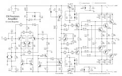
I have an idea about all you said....i have used in the Precision 1 this kind of...
circuit..... i have not appreciate....i felt the presence of the junction of the protection transistor..when inserted into the base of the first VAS transistor, the buffer, create me an audible effect that was not approved.
Also in the simulator....connecting and disconnecting the protective transistor coletor (draining to negative line by the emitter) i could see huge difference in harmonics... reason why i quit to use it....but i thank you anyway.🙂
I also have tried Cascode VAS ...no good audible results..sound became vague, not precise...i felt it was lost, loosen...not anymore referenced...the difference we have with driver emitter floating resistors or using dual resistor to the output line..i also quit the cascode VAS.... i am a maniac Ranchu...always trying..... always messing.... testing ideas..... really crazy..... i have readed all books and tried all schematics.... not normal i am..... really i have to accept that....crazy!😕
Well....thank you Ranchu..... very much appreciated your intention to help..i can feel vibrations here....very positive feelings Ranchu.... gladly or sadly i can receive these vibrations..another crazy stuff in my life.
I am creating a new amplifier (GOT).... image is pixelate...i am psychologically traumatized by pirates and piracy...this is a try to avoid them to copy... reason why i am not posting circuits anymore....here...this great forum!..the better audio forum in this world, is the source of good ideas to be copied and explored by pirates.....so.... no more open schematics.
Posting images....maybe your are talking about this kind of circuit...maybe not...please, correct me if i am wrong.
regards,
Carlos
Attachments

Last edited:
Please Ranchu...post your suggestions into an schematic
I may give it a try.
Not guarantee that i gonna use it or that i gonna discuss it...but for sure i gonna try.
If you did it and appreciate it..then go ahead using it.
regards,
Carlos
I may give it a try.
Not guarantee that i gonna use it or that i gonna discuss it...but for sure i gonna try.
If you did it and appreciate it..then go ahead using it.
regards,
Carlos
Ah yes Carlos, your images show precisely the idea I was talking about. I'm sorry it didn't work out.... you have probably tried everything I am sure!
Here is another idea you might not have tried?
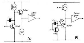
The VAS buffer is another alternative to the EF VAS. It works particularly well with a simple EF2 output stage, which I know you like.
Refer Figure F in the schematic below. I have used this circuit myself in a modified version of Rod Elliott's P3A amplifier that I built over a year ago. It sounds very good when the current source is a simple bootstrapped load and the output stage is a simple EF2 or CFP.
Attachments
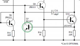
DestX, referring to post16
the bias current through Q10 sets up a DC voltage across R19.
If Vr19 is <200mV, then Q7 is OFF and Q9 sees the full effect of the drive from the input stage.
If Vr19 reaches ~400mV, then Q7 starts to turn ON and begins to steal some of the drive from the input stage. This will be audible.
If Vr19 reaches ~600mV, then Q7 is turned full ON and Q9 is turned OFF. This turns off the current through R19 and Q7 then turns back OFF. You now have a VAS oscillation with Q7, Q9 & Q10 alternately turning OFF & ON.
You must not have Q7 starting to turn ON when a valid audio signal is passing through Q9 and Q10.
This condition requires that Vr19 < ~400mVpk .
During all normal audio, Vr19 MUST be less than 400mV when Q7 is cold. If Q7 were to get hot, then the voltage for turning ON will be even lower.
These last few paragraphs require that the bias current through Q10 to drop <200mV across R19. i.e. Q10 bias must be LESS than 200mV/22r < 9mA, for the values shown in the sch. This allows the VAS current to vary by +-9mA either side of the 9mA bias value, i.e from 0mApk to 18mApk
If this condition is not met, then in operation during loud transients the protection transistor Q7 starts to turn ON and audible effects will be heard.
You can simulate this in LTspice if, unlike me, you have the computer skills.
Last edited:
- Status
- Not open for further replies.
- Home
- Amplifiers
- Solid State
- Dx Blame ST revisiting