Dx Blame ST and all Blame amplifier have invaded Rio de Janeiro, my home town
Soon, we gonna have hundreds units playing there...and the Christ Statue will start to smile:
YouTube - Rio de Janeiro City _ Brazil
YouTube - Copacabana Beach
http://www.youtube.com/watch?v=9CaarnSRWkg&feature=related
http://www.youtube.com/watch?v=G1nnC73YRCE&feature=related
http://www.youtube.com/watch?v=Ur7ud9x-moU&feature=related
Some of these videos should be reproduced in 720p.... and some of them need AGP boards.
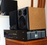
enjoy the Dx Blame and some Rio de Janeiro images...assemble one for yourself too!
regards,
Carlos
Soon, we gonna have hundreds units playing there...and the Christ Statue will start to smile:
YouTube - Rio de Janeiro City _ Brazil
YouTube - Copacabana Beach
http://www.youtube.com/watch?v=9CaarnSRWkg&feature=related
http://www.youtube.com/watch?v=G1nnC73YRCE&feature=related
http://www.youtube.com/watch?v=Ur7ud9x-moU&feature=related
Some of these videos should be reproduced in 720p.... and some of them need AGP boards.
enjoy the Dx Blame and some Rio de Janeiro images...assemble one for yourself too!
regards,
Carlos
Last edited:
Luka, my dear friend from Pollamd, built a lovely amplifier
YouTube - Blame, an awsome amplifier.mpg
regards,
Carlos
YouTube - Blame, an awsome amplifier.mpg
regards,
Carlos
relaxing piece of music. You are amusing us while we are waiting for the tests to be performed, that is kind if you dear Carlos 🙂 We will not be tired waiting for the board to arrive at your pace, we will be happy in the mean time, and enjoying your nice pieces 🙂
I am glad you like...this is to keep the thread alive
to avoid it to enter the terrible Universal Black Hole of forgotten things.
regards,
Carlos
to avoid it to enter the terrible Universal Black Hole of forgotten things.
regards,
Carlos
Dun worry, it is a matter of time and the real thing will take place, you will show us the assembled board, and you will show us your tests.
Dx blam es near complete
HI EVeRYONE I FINALLY ALMOST COMPLETED THE DX BLAM ES BUT HOW THE HELL DO I BIAS THE THING I TRIED TO FIND THE POST CARLOS PUT ON BIASING IT BUT I CANNOT FIND IT AND THIS IS THE BIT I REALLY STRUGGLE ON AND DESTROYED most of MY AMPS. THIS IS THE HEADACHE BIT FOR ME.
HI EVeRYONE I FINALLY ALMOST COMPLETED THE DX BLAM ES BUT HOW THE HELL DO I BIAS THE THING I TRIED TO FIND THE POST CARLOS PUT ON BIASING IT BUT I CANNOT FIND IT AND THIS IS THE BIT I REALLY STRUGGLE ON AND DESTROYED most of MY AMPS. THIS IS THE HEADACHE BIT FOR ME.
Attachments

Remove the rail fuses.
2Install DC voltimeter in the fuse socket with fuse previously removed.
3Switch on the amplifier power supply.
4Adjust bias trimpot to read from 3.3V to 6V over the 100 ohms series resistor.
5Check both rails.
6Move DC voltimeter to the output line.
7Off set reading should be from 3mV to 25mV, usually it is 12mV.
8Reduce it if you want, place 820 ohm, 1K, 1K2 or 1K5 resistance in parallel with R8.
9Switch your multimeter selector to ready AC volts and read the output line, no AC voltage should be there.
10 -Check once again your stand by current, if fine, them install fuses and enjoy your amplifier.
dO I REMOVE THE 100 OHM RESISTORS ONCE I HAVE ADJUSTED THE BIAS OR LEAVE THEM IN AND THEN POWER UP.
Do not remove the 100 Ohm resistors.
Leave them where they are - but do not forget to install the fuses right now!
The rail-current will flow through the fuses in normal operation - because the fuses have much less resistance than 100 Ohm!
Best regards - Rudi_Ratlos
Leave them where they are - but do not forget to install the fuses right now!
The rail-current will flow through the fuses in normal operation - because the fuses have much less resistance than 100 Ohm!
Best regards - Rudi_Ratlos
Last edited:

This is a wise amp. choice. You may have told us before but what was your PCB version? I hope when it is run in a bit, Joka, you can give us your impressions.
BTW, who is that handsome young dude?
BTW, who is that handsome young dude?
Remove the rail fuses.
2Install DC voltimeter in the fuse socket with fuse previously removed.
3Switch on the amplifier power supply.
4Adjust bias trimpot to read from 3.3V to 6V over the 100 ohms series resistor.
5Check both rails.
6Move DC voltimeter to the output line.
7Off set reading should be from 3mV to 25mV, usually it is 12mV.
8Reduce it if you want, place 820 ohm, 1K, 1K2 or 1K5 resistance in parallel with R8.
9Switch your multimeter selector to ready AC volts and read the output line, no AC voltage should be there.
10 -Check once again your stand by current, if fine, them install fuses and enjoy your amplifier.
This is only the initial set up of the amp, to ensure it is working in a safe operating region. You need to adjust Vbias accurately by measuring the voltage across both the emittor resistors, 55 mV if I remember correctly.
The picture was mine with 18 years old....in 1969
The adjustment, as Greg said, need an extra step, to check the output transistor current, and it is made reading the voltage developed over the power transistor emitter resistance.
As you know, when current crosses a resistance develops a voltage into the resistance extremes, this DC voltage can be measured, and using ohms law we can obtain the current.
For instance, try to adjust in order to measure 1 milivolt DC...or, adjust to obtain this reading as a result.... and if your power transistor emitter resistance is 0.22 ohms...them apply the ohms law formula....... to obtain a current we divide the voltage expressed in volts by the resistance expressed (written) in ohms:
0.001V divided by 0.22 Ohm....... 0.001/0.22=0.0045A ..... so, this means that a single milivolt measured over 0.22 ohms resistance will result in 4.5 miliamperes of current flowing...and this is more than good, this is perfect for a class AB amplifier.
We must be carefull about that.... say...it is easier to read and to have 10 milivolts measured there....seems to be something more decent...but observe this will result in a huge current....as 10 milivolts will result in 45 miliamperes... a lot of energy waste...having some production of heat.
Heat, watts of heat,you can calculate multiplying the voltage you have in your power transistor.... the voltage measured from colector to emitter, by the current....this means 35V multiplied by 0.045A..... and this results in 1.575 watts....and this happens in both transistors...means 3 watts will be heating your heatsinks and this heat is result of nothing..no audio produced..just heat!... waste of energy only... reducing your heatsink efficiency with that heat doing nothing usefull for us.
Having 10 output pairs you may have 30 watts of heat being wasted...almost alike a small soldering iron...just heat being dissipated, and if you do not intend to cook eggs over your heatsink,a good idea is to have some carefull with this measurement and to check your readings twice.
Adjusting this way..... checking only the power emitter resistances, is much better than to check the global, total amplifier current consumption, because if you have the same current in the PNP and NPN transistors, or, the same current in the upper and lower rail, this means also your amplifier is ballanced and your off set is low...so, it is a superior method, that can be complementary to the traditional way we use, or even better.
regards,
Carlos
will perform the steps but just waiting to be paid by customer then i buy multimeter to setup the amp. old multimeter malfunctioned.
Take the time you need..... not needed to make it in a hurry
The cheap ones, the yellow ones, from China, works fine.
Of course, if want the best, then go to Fluke.
regards,
Carlos
The cheap ones, the yellow ones, from China, works fine.
Of course, if want the best, then go to Fluke.
regards,
Carlos
- Status
- Not open for further replies.
- Home
- Amplifiers
- Solid State
- Dx Blame ES .... based into the Blameless, i am trying a new amplifier