You can use from 220n to 2.2uf
I have tried several values...better to use 270n..... or 274 or 0.27uF
The suckout works when the amplifier clips.... as you will not be listening it clipping, the value is not so important..even if you remove it will not perceive difference...at the simulator distorts 0.001% more (THD) when i have used values higher than 330n..... this will be sensed, perceived, during distortions only.
It sucks charges during the crossover moments.... helps transistors to change it state.
Also rail resistance can be 22ohms, 27 ohms, 33ohms, 39 ohms, and 47 ohms...better to reduce in the place to increase.
regards,
Carlos
Hi here are the download sheets for parts, schematic, pcb layout. The schematic is 1.3, pcb layout image is 1.4c. you also get parts list sheet for 1.3 with c18 changed to 220nf. i changed it to 220nf on sheet by reading through the threads but carlos and gang got their first.
Attachments
Here a recording made using digital camera... Dx Blame ST pumping full power
a little bit more than 100 watts, the speaker is 150 watts only ...using a simple and old speaker...something common...to show you it can produce good sound in almost any speaker.
The power was adjusted in the threshold of clipping..the meter reaching " 0 VU " seems it is entering the clipping... meter balistics was considered of course while adjusting the meters.... inertia and weigth in movement.
The digital camera microphone was obstructed by my fingertip, then no digital camera microphone saturation (Fujifilm Finepix A900)... naturally the high frequencies where lost this way.... microphone was covered by my finger.
Observe this amplifier main characteristic, distortion is very low:
YouTube - Dx Blame ST full power
Speaker is 4 ohms...anything special... simple speaker, old speaker enclosure... a lot of holes on it... dampened with humidity (water), refurbished drivers, old condensers and capacitors in the passive crossover...and even this way sounds fine!
regards,
Carlos
Hi
Thanks for posting the docs. for ES version together, Joka this is very convenient.
regards
Ian
Thanks for posting the docs. for ES version together, Joka this is very convenient.
regards
Ian
 For completeness, here are the versions I have collected. Sorry, I accidently renamed all files into the "Greg logic" standard.
 I have ordered components from maplin since they accept paypal. Using paypal can be expensive. Maplin have the bc556 etc but they have bc556b and c version transistor and they are npn and also pnp which is confusing. However they lack power resisters or metal film resistors which are1/4w they have 0.6w.
I was just about to order the 2w version all of them for the board until i looked at the booard carefully them resistors never fit on the board it so tiny.
got most of film caps, eletric cap etc. lacking in low powered transistors looked on ebay but some of them look like they been chewed or home made.
@ Ian and Joka22,
both of you have (IAN: will have - the PCBs are on its way to you - Australia: that is a long distance away from Germany) layout Revision 1.4 PCBs.
The one and only one difference between Revision 1.4 and 1.5 layout is a 10 Ohm resistor (R32) that Carlos introduced on the second VAS emitter Q7 for stability reasons.
Carlos: pls correct me I if I am wrong.
I cut the traces there, inserted the 10R and listened again.
My ears have neither been delighted nor shocked.
Did I "hear" any difference? No.
My audiophile feeling said: "Revision 1.3 schematics was the one I fell in love with."
So: I unsoldered the 10R and bridged the gap.
You both are "DIY'ers": you should feel, hear (or not) the audible difference by yourselves. Does not take much time.
Best regards - Rudi_Ratlos
both of you have (IAN: will have - the PCBs are on its way to you - Australia: that is a long distance away from Germany) layout Revision 1.4 PCBs.
The one and only one difference between Revision 1.4 and 1.5 layout is a 10 Ohm resistor (R32) that Carlos introduced on the second VAS emitter Q7 for stability reasons.
Carlos: pls correct me I if I am wrong.
An externally hosted image should be here but it was not working when we last tested it.
I cut the traces there, inserted the 10R and listened again.
My ears have neither been delighted nor shocked.
Did I "hear" any difference? No.
My audiophile feeling said: "Revision 1.3 schematics was the one I fell in love with."
So: I unsoldered the 10R and bridged the gap.
You both are "DIY'ers": you should feel, hear (or not) the audible difference by yourselves. Does not take much time.
Best regards - Rudi_Ratlos
An externally hosted image should be here but it was not working when we last tested it.
i recived the boards from ekart they execelent and look so tiny you put in your pocket it like a credit card but it thick and with good solder mask.
Good... sadly we have not these thing in Gerber files
this way would be even easier to people order boards etched professionaly made.
regards,
Carlos
this way would be even easier to people order boards etched professionaly made.
regards,
Carlos
Volker,
you are just around finishing your 2nd BlameES, aren't you?!
I will visit you ASAP.
Rudi
you are just around finishing your 2nd BlameES, aren't you?!
I will visit you ASAP.
Rudi
An externally hosted image should be here but it was not working when we last tested it.
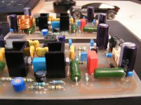
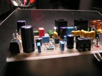
Yes, it´s right. These are the same PCBs joka22 got from me, the original ones.you are just around finishing your 2nd BlameES, aren't you?!
They are very small and lovely 🙂
PSU is missing, i will do it next time it´s raining ;-)
Yeah, Yippie, 
this is BlameES 1.3 schematics - 5 micas - the one 1 LOVE
Rudi Ratlos
this is BlameES 1.3 schematics - 5 micas - the one 1 LOVE
Rudi Ratlos
An externally hosted image should be here but it was not working when we last tested it.
Heheheh.... i will transform my ST into this model too
I remember it was less stable but sounded sooooooo good!
But i have the obligation, the duty to inform.... do it under your own risk folks... the 18pf creates a small oscilation superimposed to the positive half wave (in the NFB, remove that one!)... and the 100 ohms resistance in the first VAS is dangerous too...if your amplifier starts to oscilate and burns fuses do not complain to uncle Charlie!...i have made the ST to have it more stable (and more stérile too).
If you modify and faced problems, do not complain, nor blame, nor trash my fame.
ahahahahaha!🙂🙂🙂
The removal of that 18pf capacitor was because of Kroto suggested me to do that and i found he was rigth.... Kroto's modification.
regards,
Carlos
Last edited:
.... and do not forget to post your obligation, Carlos, my friend:
"DO NEVER insert a 20 KHz rectangular square wave into the BlameES while at the same time exposing it to the feedback of a microphone ..."
BUT: it sounds so beautifully if you do not ...
Rudi_Ratlos
"DO NEVER insert a 20 KHz rectangular square wave into the BlameES while at the same time exposing it to the feedback of a microphone ..."
BUT: it sounds so beautifully if you do not ...
Rudi_Ratlos
An externally hosted image should be here but it was not working when we last tested it.
Now you can insert a 20 Khz square wave having high levels
alike 3 volts peak to peak in the input, and also entering microphonic sound of acoustic feedback and it will not be destroyed.
Was that hell transformer, the defective toroidal that was producing all the mess and troubles i had..... more than 15 power transistors lost because i could not believe that something was wrong with the transformer...i paid because stubborn and stupid.
When i decided to run three wires from another transformer, from another amplifiers... AC wires..and them i have connected them to my supply rectifier and filters and all trouble finished...oscilations gone when overdriven!
Here, you can see in this video.... you see the Dx amplifier, the standard one, adjusted (modified) to work with 55 volts DC.... it was working... a long time sounding in my home.... stable, well adjusted, good bias, good off set...nice one..then i decide to install it in the toroidal transformer supply.... that one having 48 volts.....so...be attention.... the amplifier worked and was adjusted to higher voltage (55V) and them i have installed into a lower voltage (48V).
First moment, the resistances i have installed in series with the secondary burned immediatelly as a flash..the amplifier was shorted!... the output burned instantaneously...i had not time enough to say sh..
Then i replaced the output, checked the amplifier measuring resistances and i have perceived anything more was damaged...drivers measured.... anything wrong... them i have replaced the toroidal secondary output series resistances (a forum friend suggestion)... and i switch the amplifier on once again.... the output gone once again...watch the movie.
The hell toroidal created the trouble..have burned Aksa 55, have burned Dx amplifier and others too...and i was stupid to understand anything more than the supply could be the faulting part....i had suspections about my snubberized supply (that never have created troubles) and i have removed all snubbers, bypasses and filters...but i was not believing the toroidal have created the problem...i really think..the day i decide to dismount the toroidal i will find something..maybe the core is broken and glued..having bad contact, capacitance and spikes:
YouTube - Aaaagh, that transformer again!
regards,
Carlos
Pretty Volker... very good picture..nice board you have made
You are very good..an artist alike Rudi...you both are great.
The Dx Germany Division makes me very proud.
regards,
Carlos
You are very good..an artist alike Rudi...you both are great.
The Dx Germany Division makes me very proud.
regards,
Carlos
- Status
- Not open for further replies.
- Home
- Amplifiers
- Solid State
- Dx Blame ES .... based into the Blameless, i am trying a new amplifier