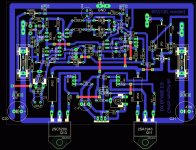
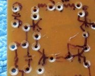
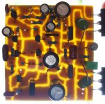
Danilo Coke is also building, he has prepared this board that will be revised
Not checked, just to show you we are moving our bodies to do something.
Soon the amplifier will be tested with THREE different boards, to be absolutelly sure it is stable (or not)
regards,
Carlos
Not checked, just to show you we are moving our bodies to do something.
Soon the amplifier will be tested with THREE different boards, to be absolutelly sure it is stable (or not)
regards,
Carlos
Attachments


How about something a bit different than traditional, like error correction on the output stage...
http://www.diyaudio.com/forums/soli...veral-unique-allison-based-output-stages.html
http://www.diyaudio.com/forums/soli...veral-unique-allison-based-output-stages.html
Good idea to the next one dear Eva...you know, i have been watching that
since a long time ago, and soon this will happens, now i will wait ONE forum folks assemble and at least three guys from my Orkut, them i will understand my job was done.
I was watching this yesterday, while i was uploading some schematics do my dear friend Canadien, Monsieur Gaetan.
I would like to understand, more than i know (not too much) the advantages, the off set correction is obvious, but tell me something more dear Eva.
I have to keep myself in focus, not to delirate too much and start several things at same time, this is my problem, only two hands and the day having only 24 hours, i would like 12 hands to work faster and to do several things at same time...i cannot...sadly i cannot.
Please, do me a favor Eva, tell us something about error correction, in simple words to us to understand clearly what this really does, the results we may have, the real advantages.
Will read "simulation analisis of..... "
regards,
Carlos
Attachments
Last edited:
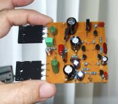
Some images for my dear friends, ... today i will build another Dx Blame ES
The peanut image is because i thing forum folks (not all forum folks) needs more energy to assemble things,...maybe your wife is also complaining my dear..what about some more peanuts in your life?
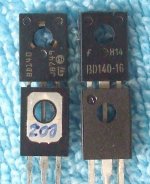
BD139/140 transistors, they are good, they can work at 100 Megahertz, i have built several transmitters using this one, Radio Frequency transmitters operating 108 Megahertz, also i have used as drivers (with some losses) in 144 Megahertz Radio Amateurs VHF transceivers, also in CB Radio Transceivers ad 10 meters SSB transceivers... do not tell me they are not good.... i will turn mad imediatelly, i am sure they are very good for audio.
Observe there are models that has metal surface to transfer heat to the heatsink, also it puts the colector into the heatsink metal surface, this is not good as some parasitic capacitances may bother you....there are other model that does not have metal exposed, all black plastic (things you give a shape, plasticity) cover.
I do not use MJE340/350 because i do not have them, they are weak, the leads broke whenyou bent them, they are easy to oscilate, in the Simulator (Multisim 10) they usually result in bigger THD....i do not use them because i do not like them, do not trust them, this one you can say is not good and i will not be mad with you.
regards,
Carlos
The peanut image is because i thing forum folks (not all forum folks) needs more energy to assemble things,...maybe your wife is also complaining my dear..what about some more peanuts in your life?
BD139/140 transistors, they are good, they can work at 100 Megahertz, i have built several transmitters using this one, Radio Frequency transmitters operating 108 Megahertz, also i have used as drivers (with some losses) in 144 Megahertz Radio Amateurs VHF transceivers, also in CB Radio Transceivers ad 10 meters SSB transceivers... do not tell me they are not good.... i will turn mad imediatelly, i am sure they are very good for audio.
Observe there are models that has metal surface to transfer heat to the heatsink, also it puts the colector into the heatsink metal surface, this is not good as some parasitic capacitances may bother you....there are other model that does not have metal exposed, all black plastic (things you give a shape, plasticity) cover.
I do not use MJE340/350 because i do not have them, they are weak, the leads broke whenyou bent them, they are easy to oscilate, in the Simulator (Multisim 10) they usually result in bigger THD....i do not use them because i do not like them, do not trust them, this one you can say is not good and i will not be mad with you.
regards,
Carlos
Attachments


What's the problem with my boards?
ahahahahah!...they are pretty!
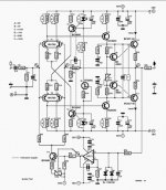
Easy to understand, the schematic is there, watch and you will see, it is simple and stone aged, the simple and direct transference from the schematic to the board, then you drill hole to the part's leads and in the other side you connect them using lines and last you join the wires into small islands... between islands you use Dremmel high speed machine to erode and remove copper, them you will have copper islands...Ready!
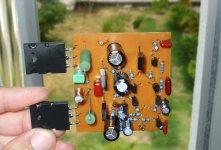
Build Dx Amplifiers folks, and come here to say if you dislike...maybe you will be the first and great doing that, everybody likes!
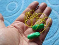
To listen other amplifiers, with some exceptions of course (your own amplifier my dear reader), you will need these earplugs.... listen something will not produce pain in your......... hehehehe..... ears!
I will build another amplifier today!...will listen new amplifier today!...will have pleasure, once again and today!..while you will listen nothing new or special because you did nothing today!
regards,
Carlos
ahahahahah!...they are pretty!
Easy to understand, the schematic is there, watch and you will see, it is simple and stone aged, the simple and direct transference from the schematic to the board, then you drill hole to the part's leads and in the other side you connect them using lines and last you join the wires into small islands... between islands you use Dremmel high speed machine to erode and remove copper, them you will have copper islands...Ready!
Build Dx Amplifiers folks, and come here to say if you dislike...maybe you will be the first and great doing that, everybody likes!
To listen other amplifiers, with some exceptions of course (your own amplifier my dear reader), you will need these earplugs.... listen something will not produce pain in your......... hehehehe..... ears!
I will build another amplifier today!...will listen new amplifier today!...will have pleasure, once again and today!..while you will listen nothing new or special because you did nothing today!
regards,
Carlos
Attachments

I have received your email dear Mark, and soon i will send you what you have asked
Wait, please, one day more, i have to contact the guy and wait him to send me to them send to you.
thanks by your kind offer, already accepted in advance.
au revoir.
votre ami Brèzilien
Charle
Wait, please, one day more, i have to contact the guy and wait him to send me to them send to you.
thanks by your kind offer, already accepted in advance.
au revoir.
votre ami Brèzilien
Charle
Boys, i am running against the clock, the year is going to the end
and i would like to offer you, as soon as possible, news about four different board assembled and tested.
The one i will build today.
The Danilo Coke layout
Todd Johnson official Corporation Layout
And the one i have already assembled, the one gave me some bad times
This material, now posted, was checked by Taj, but you know, we are humans, despite he is much better than i am doing such kind of job (revision), he is younger and more clever, has better spatial intelligence, But even this way, something can be missed, i will check at nigth, as i have things to do.
I have to walk along the beach to see the girls passing by, very inspirating this to me.
And build the board is ready to go!
regards,
Carlos
Attachments
Last edited:
Here's PDF of the copper and a clear picture of the layout (the layout PDF was too big for diyAudio.)
A couple items to note:
A couple items to note:
- The power resistors are Mills/Huntington brand (non-inductive) which are substantially smaller than the typical ceramic white square ones. Please substitute with whatever you can find that fits. The BoM shows the digi-key part# for the Mills resistors if you want to go that way.
- Sadly, I haven't spent the time to learn PCB software, so I draw these with illustration software, which I am very fast with. But there is no circuit checking or standard parts libraries this way. Be afraid, this has not been tested.
- The PCB was designed to mount 'sandwich style' on a heatsink ledge (or L-bracket attached to the heatsink.) The PCB mounts under the ledge, the output devices mount on top of the ledge. If you are not mounting this way, you can cut off the extra PCB material.

Attachments

Last edited:
... he is younger and more clever, has better spatial intelligence
... and has recently acquired a sizable collection of anal smoke. 😉
..Todd
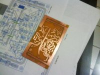
The black line layout, to use hot iron thermicall transference of toner to board
is inverted, we gonna fix that.
Also we gonna produce the image to photo sensitive transference, ligth projection, when the copper line appear in white.
Soon.....
regards,
Carlos
is inverted, we gonna fix that.
Also we gonna produce the image to photo sensitive transference, ligth projection, when the copper line appear in white.
Soon.....
regards,
Carlos
Dx home board production
Craftsman style
YouTube - Audio amp Dx Blame ES, board artisan style
regards,
Carlos
Craftsman style
YouTube - Audio amp Dx Blame ES, board artisan style
regards,
Carlos
Despite i love the sonics, i continue having strong suspections this circuit is not
stable, i am having troubles with the Craftsman style board too.
This way, i suggest to friends, the ones interested to build, to wait the results from the Brazilian Orkut Audiophile Communitty results.
There we gonna test Taj board layout and another layout prepared by Danilo...if those ones presents some kind of problem, then i will confirm my suspections.
I know it it something to trust, inspired by Doctor Douglas Self Blameless design is something really strong, but believe me, even this way can be a lovely sounding "lemmon".
48 years building amplifiers made me perceive when amplifiers start to present strange things, better do stop with them, there are units very unstable, in my life i have never good relationship with CCS.... and suspections goes there, because removing and installing the traditional zener regulator everything turns stable once again.
There are several signs we go learning while buiding and having several units presenting problems, i am recognizing these signs.
Do not build before my OK!
regards,
Carlos
Last edited:
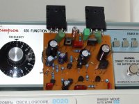
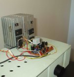
My small board, Craftsman style is operating fine.
So, second board operating fine, my Orkut friends are building others, using other boards.
This resistance must be 100 ohms, or even 82 ohms, this is the value adjusted in the production line (ahahahahah!... Corporation is this way)
regards,
Carlos
So, second board operating fine, my Orkut friends are building others, using other boards.
This resistance must be 100 ohms, or even 82 ohms, this is the value adjusted in the production line (ahahahahah!... Corporation is this way)
regards,
Carlos
Attachments

Last edited:
- Status
- Not open for further replies.
- Home
- Amplifiers
- Solid State
- Dx Blame ES .... based into the Blameless, i am trying a new amplifier