Hello everybody.
I am new here, by profession I am electronics engineer, but never worked with tubes as professional, although audio (up to now - discrete and IC only) has always been my passion 🙄
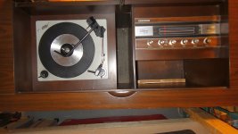
I recently bought from Craiglist old DuMont Stereo Console, late 50's, solid wood, all-tube design. ALL WORKS, just usual scratch on pots.
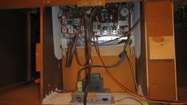
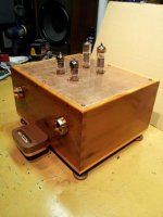
My initial intention was to use it as a separate AM/FM/Receiver or even just as small tube amp. So I opened the box and started investigating what I've bought, made some photos and have discovered the complete paperwork inside (no exact date of manufacturing, though), including schematic.
The fact I've discovered so far about it:
1. The Console as a whole is in outstanding cosmetic condition - just few scratches on the corners, but otherwise looks like new - old lady I bought it from was first and the only owner. The original labels says:
DUMONT TELEVISIONS & RADIO Montreal, Canada, Model DS-136. Google gave me nothing on that... 😡
2. The turntable is BSR (Birmingham Sound Reproducers) Made in Great Britain - pretty ubiquitous old timer brand for low-end turntables. It's automatic, with ceramic cartridge which sounds terrible in the condition it is now. Cartridge is BSR N-50, needle type - 133 - absolutely NO INFO about the replacement of these...🙄
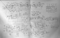
3. Radio/Amp works and sounds amazing for the age. I am attaching the schematic, among with photos. The amp (the part I am most interested in) is based on 12AX7 pre-amp and dual 50EH5 power amp (datasheet shows 1.4W output power per channel). The sound of the radio is AMAZING - dead-lock on every station and even AM sounds like FM in modern radios! 😉
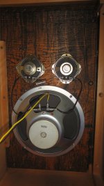
4. Speakers are one 8" woofer and two 2" tweeters, Made in Japan. Again - condition is like new, no tin sound, no rattling or clanking.
Well - that is about the system I've got, described in short. The million dollar question is:
"What is the best to do with it?"
I see the following options:
1. To restore (recap, clean and refurbish as much as I can keep to original) the WHOLE BOX. I am very hand and have restored electronic items all my life, so that's not a problem. The problem is that the unit is too big to keep it as an original stereo in a room. Any idea how much unit like this in mint condition with all original papers may cost retail?
2. To get the Receiver Module out and put it in a nice stainless/aluminum/plexi box with all in/outs connectors, etc. Any idea will that worth the effort? Again - making a nice boxes is my passion, so I don't mind the extra work, the question is will the amp worth it?
3. To keep the pre-amp/amp only and make a complete new case, as described in #2.
What according to you would be the best choice for me?😕
I am completely open to any suggestions and will not feel offended from straight, but honest professional opinions, so feel free to advise! 😱
Thanks sin advance, guys!
I am new here, by profession I am electronics engineer, but never worked with tubes as professional, although audio (up to now - discrete and IC only) has always been my passion 🙄
I recently bought from Craiglist old DuMont Stereo Console, late 50's, solid wood, all-tube design. ALL WORKS, just usual scratch on pots.
My initial intention was to use it as a separate AM/FM/Receiver or even just as small tube amp. So I opened the box and started investigating what I've bought, made some photos and have discovered the complete paperwork inside (no exact date of manufacturing, though), including schematic.
The fact I've discovered so far about it:
1. The Console as a whole is in outstanding cosmetic condition - just few scratches on the corners, but otherwise looks like new - old lady I bought it from was first and the only owner. The original labels says:
DUMONT TELEVISIONS & RADIO Montreal, Canada, Model DS-136. Google gave me nothing on that... 😡
2. The turntable is BSR (Birmingham Sound Reproducers) Made in Great Britain - pretty ubiquitous old timer brand for low-end turntables. It's automatic, with ceramic cartridge which sounds terrible in the condition it is now. Cartridge is BSR N-50, needle type - 133 - absolutely NO INFO about the replacement of these...🙄
3. Radio/Amp works and sounds amazing for the age. I am attaching the schematic, among with photos. The amp (the part I am most interested in) is based on 12AX7 pre-amp and dual 50EH5 power amp (datasheet shows 1.4W output power per channel). The sound of the radio is AMAZING - dead-lock on every station and even AM sounds like FM in modern radios! 😉
4. Speakers are one 8" woofer and two 2" tweeters, Made in Japan. Again - condition is like new, no tin sound, no rattling or clanking.
Well - that is about the system I've got, described in short. The million dollar question is:
"What is the best to do with it?"
I see the following options:
1. To restore (recap, clean and refurbish as much as I can keep to original) the WHOLE BOX. I am very hand and have restored electronic items all my life, so that's not a problem. The problem is that the unit is too big to keep it as an original stereo in a room. Any idea how much unit like this in mint condition with all original papers may cost retail?
2. To get the Receiver Module out and put it in a nice stainless/aluminum/plexi box with all in/outs connectors, etc. Any idea will that worth the effort? Again - making a nice boxes is my passion, so I don't mind the extra work, the question is will the amp worth it?
3. To keep the pre-amp/amp only and make a complete new case, as described in #2.
What according to you would be the best choice for me?😕
I am completely open to any suggestions and will not feel offended from straight, but honest professional opinions, so feel free to advise! 😱
Thanks sin advance, guys!
Attachments
I've disassembled a couple of these, Having the schema is nice, thanx.
At some point a pr of 50EH5 monobloks.
The 8" is an RSC. If you are lucky they are the ones with isophon comes. Even the others are quite reasonable.
The turntable is of little utility.
dave
At some point a pr of 50EH5 monobloks.
The 8" is an RSC. If you are lucky they are the ones with isophon comes. Even the others are quite reasonable.
The turntable is of little utility.
dave
Recap it and shine it up with teakoil, it would be a sin to kill a jewel like that, and even if its dificult to get a new ceramic pu. it is not impossiple.😉
You already seem to be clued into the fact that the BSR TT is a POS. It should not be allowed near precious LPs. Piezoelectric cartridges can literally scrub the HF info. out of record grooves. 🙁 Also, high tracking forces induce general wear.
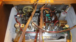
The circuitry is quite interesting; series heater strings, but strictly AC operation. While it's low power, it's not especially cheap. 🙂 Notice the tertiary, local cathode, NFB windings on the O/P transformers. That cost some money.
Eliminating C68, C69, and R50 is a must do. Along with that, install a proper, 3 wire/safety grounded, power cord.
Replacing all electrolytic caps. in "vintage" units is a matter of routine.
I would rework the 1/2 wave rectified B+ PSU into a full wave bridge using 4X UF4007s, but you have to pay very careful attention to the grounding caps. in the tube heater setup. Install parts of a vastly higher working voltage.
Replacing any of the RF/IF tubes will require realignment.
The Russian 6H2Π (6n2p) is not a plug in substitute for the 12AX7/ECC83.
Trying some borrowed HIGH efficiency horn speakers with the Dumont electronics is (IMO) worth a shot.
Last edited:
You can use 6Н2П tube instead of 12AX7, but powering it's filament from 6.3V supplied for pilot lamps, and replacing 12AX7 filaments by resistor, to provide 12V voltage drop on it.
Note the fact that it has a stereo multiplex decoder built into the FM tuner dates the console to sometime after April 1961 as the Canadian FM stereo broadcast standard approval of the Zenith/GE system by the DOC presumably followed the U.S fairly quickly.
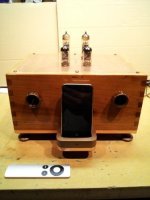
I rescued an old Grundig NF1 amp from a Grundig Majestic console (8.5wpc, ELL80) and made it into an i-pod dock for my wife - maybe that's an idea for ya. It even charges the ipod; the copper top has acquired a nice patina over the last year since I built it.
See pictures.
See pictures.
Attachments

Thank you very much for the advices, whoa, that was fast, amazing forum! I really, really appreciate the help!
I still have a lot of homework to do (cleaning is already done and I have removed the main unit from the wooden box) - learning and start making improvements without (for now) altering the original functionality.
I must assure you, though, that at least for a while I will keep everything "backward compatible" - e.g. I can always put everything back.
I'll start with recaping and new power cord.
Quick questions:
1. Eli Duttman, should I replace or remove R50 and C68, C69. At my understanding it's nice to have AC filer, no?
2. Changing the rectifier to full wave is very good idea, but this would increase the effective DC voltage, right? Will that change the bias?
3. What do you mean exactly by "HIGH efficiency horn speakers" - speakers with mechanical design allowing high acoustic output? Can you give me a link?
4. Are there a chances to use at least ceramic cartridge with that unit?
Did anybody do that with old BSR TT?
Wavebourn, thank you for the clarification, I knew that some mods were needed, thanks for details.
kevinkr, thanks for the note - I assume that will consider the console to be "Early 60's", right? Clips on YouTube showed "Late 60's" Dumont consoles with solid-state already... 🙄
Once again - thanks everybody, keep going, I will post the updates too!
Cheers!
Thank you very much for the advices, whoa, that was fast, amazing forum! I really, really appreciate the help!
I still have a lot of homework to do (cleaning is already done and I have removed the main unit from the wooden box) - learning and start making improvements without (for now) altering the original functionality.
I must assure you, though, that at least for a while I will keep everything "backward compatible" - e.g. I can always put everything back.
I'll start with recaping and new power cord.
Quick questions:
1. Eli Duttman, should I replace or remove R50 and C68, C69. At my understanding it's nice to have AC filer, no?
2. Changing the rectifier to full wave is very good idea, but this would increase the effective DC voltage, right? Will that change the bias?
3. What do you mean exactly by "HIGH efficiency horn speakers" - speakers with mechanical design allowing high acoustic output? Can you give me a link?
4. Are there a chances to use at least ceramic cartridge with that unit?
Did anybody do that with old BSR TT?
Wavebourn, thank you for the clarification, I knew that some mods were needed, thanks for details.
kevinkr, thanks for the note - I assume that will consider the console to be "Early 60's", right? Clips on YouTube showed "Late 60's" Dumont consoles with solid-state already... 🙄
Once again - thanks everybody, keep going, I will post the updates too!
Cheers!
The Hedlund Horn is an example of what I mentioned. The "full range" driver used is by Lowther and, in some versions, can produce a SPL of over 100 dB. at a 1 M. distance, when driven by 1 W. That's the kind of speaker sensitivity needed to do serious listening with an amp like your Dumont and its "flea power". Google Lowther Medallion for another example.
Scan the archives for "Death Capacitor". Unfortunately, C68, C69, and R50 fall into that category. 🙁 Please adhere to contemporary safety standards.
Please provide a close in photo of the BSR headshell and cartridge. There's an outside chance of being able to mount a low cost mag. cart. in place of the piezoelectric POS. Ceramic carts. are piezoelectric and to be avoided. Frankly, it's better to scrap the BSR TT and install a "vintage" Technics, Pioneer, or BIC TT intended from day 1 for use with mag. cartridges. Jim Hagerman's "Bugle" phono preamp is a quite decent, inexpensive, solution to the problem of interfacing a mag. cart. to the Dumont electronics.
Full wave rectification will not increase the nominal voltage of the B+ rail. Remember, a cap. I/P filter charges up to 21/2 X the AC RMS voltage and drifts downward, under load. Switching to full wave rectification doubles the ripple freq. (twice as many charging pulses) and increases the effectiveness of the PSU filter. 😀
Hi guys,
I have a question about recaping:
I have one "quad" capacitor - 2 x 100uF + 2 x 50uF (4 caps in one body) rated to 180V. It's RIKEN, Made in Japan.
Is there a way to find brand new cap with same structure (4-in-one) or I have to replace it with 4 separate ones?
In any case - what is the brand and source you'd recommend (otherwise I have a lot of sources for standard EL caps, of course, I can use).
Also - do you usually install caps with higher voltage rating or 180V is good enough?
Thanks.🙄
Oh, forgot - one quick one:
There is FM Indicator component on the schematic (bottom left), NE2E. Looks like lamp of some sort (neon?), but it never lights up, even when when tuned on FM STEREO (clearly heard as stereo on the speakers).
How I can check it, what voltage I would expect to be powered by and if gone - is there a way to replace it?
Thanks! 🙂
If there's room under the chassis some just unhook the old can cap and leave it for looks and buy individual or combo caps. It's more affordable and some replacement can caps have been on the shelf too long so fail early.
JJ makes affordable caps and you can buy ones with increased voltage with no problem. Nichcon & Panasonic are other good names in affordable ones.
You can also get a clamp and put the new cap in place of the old can cap. You probably will only find a suitable dual section only so you will have to put the smaller dual section under the chassis. Use heat shrink tubing so no shorts occur.
Keep the old can for the restorers if you sell the unit.
There is a company that will make you an exact can cap to watever specs you want that has a great reputation on the forms.
http://hayseedhamfest.com/index.html
Randy
Last edited:
Oh, forgot - one quick one:
There is FM Indicator component on the schematic (bottom left), NE2E. Looks like lamp of some sort (neon?), but it never lights up, even when when tuned on FM STEREO (clearly heard as stereo on the speakers).
How I can check it, what voltage I would expect to be powered by and if gone - is there a way to replace it?
Thanks! 🙂
Yes, that's a neon lamp. You can get a replacement from Allied for 41 cents. 😀 That sort of lamp needs a bit under 70 VAC to "strike". You may have faulty driving circuitry, instead of a failed indicator.
Oh, forgot - one quick one:
There is FM Indicator component on the schematic (bottom left), NE2E. Looks like lamp of some sort (neon?), but it never lights up, even when when tuned on FM STEREO (clearly heard as stereo on the speakers).
How I can check it, what voltage I would expect to be powered by and if gone - is there a way to replace it?
Thanks! 🙂
The tube V6 sits around a tuned circuit that detects the 19kHz pilot tone used for stereo. The left hand end (on the schematic) of the neon sits pretty much at the HT voltage that feeds the anode of V6B via the coil. The right had end of the neon is taken to a lower voltage determined by the setting of the pot. With no stereo being received, there will be little AC voltage on the anode of V6B. I think that the pot should be adjusted under these conditions to light the neon, and then backed off a little so that the neon is just extinguished. Then when there is a 19kHz pilot tone present (when receiving a stereo broadcast) the amplitude of the signal on the anode of V6B will significantly increase. This will be enough to cause the neon to start to glow.
As for it not glowing at all - it could be the neon - as said above, neons are quite inexpensive. It is also very possible that the pot has failed since it has the HT supply across it. It could be that the wiper connection is open circuit, or that the resistance track itself has gone open due to heating and age. That part should also be replaceable but you'd need to take some care to choose a part that can handle the voltage and possible heat dissipation.
Neons work with AC or DC voltages - this one has a large DC voltage with a smaller AC component on top. I would expect that when off there should be around 70 volts DC across the neon, but the actual voltage that you see will depend on the pot setting, and the "just off" voltage will depend on the specific characteristics of the neon itself.
One extra thought - if the stereo decoder is working, do not be tempted to make any adjustment to the tuned coils - they can be difficult to set up correctly without the right test gear. Adjusting the pot for the neon is OK, but don't take the wiper fully to the grounded end of the pot - that will effectively short out the HT supply (from R23 / C38A) that feeds V6 (through coil T8) down to ground through the neon, damaging at least the neon and the pot in the process. It may be that has already happend in the past. (If I designed it, there would be a resistor of at least 10K in the ground leg of the pot to prevent this from happening and it would have no real effect on the operation of the circuit.)
Last edited:
12E1, thanks a lot for the info.
Well, the quick measurements (DC only) showed... strange things:
1. When RADIO is OFF - I can measure 127V on V6B anode (pin6) and 85V on the pot's side.
2. When RADIO is ON - I can measure 106V on V6B anode (pin6) and 69V on the pot's side.
3. Strange thing is that no matter what FM Mode I choose (FM STEREO, FM AFC or FM) - voltages are as #2 and never change. In FM STEREO Mode I can clearly distinguish stereo reception (Mono at FM AFC and FM Modes).
4. More strange is that #2 voltages stay even when I am NOT tuned to a station.😕
The pot is sealed and never been turned.
5. When I move the pot - the neon LIGHTS UP. Unfortunately - it stay always lit - no matter what RADIO MODE I am switching on, it is lit even on PHONE mode.
Questions:
1. Where the pilot 19kHz signal comes from?
2. If I have STEREO reception, but nothing changes at pin 6 of V6B - should I blame the tube - is the tube for FM STEREO presence indication only?
4. I still didn't recap the unit - is it possible to blame C44?
Thank you!
Well, the quick measurements (DC only) showed... strange things:
1. When RADIO is OFF - I can measure 127V on V6B anode (pin6) and 85V on the pot's side.
2. When RADIO is ON - I can measure 106V on V6B anode (pin6) and 69V on the pot's side.
I am not sure what the correct voltages would be, but 106 - 69 = 37 volts - that's almost certainly too little, since it would require a very large AC signal on top to get a peak voltage that would cause the neon to light.
3. Strange thing is that no matter what FM Mode I choose (FM STEREO, FM AFC or FM) - voltages are as #2 and never change. In FM STEREO Mode I can clearly distinguish stereo reception (Mono at FM AFC and FM Modes).
And if you tune a very weak signal, can you hear that there is no stereo decoding taking place (the audio would then be in mono but probably with some hiss)?
4. More strange is that #2 voltages stay even when I am NOT tuned to a station.😕
Actually I do not expect that the DC voltages would change much. But you would find an AC signal at 19kHz present on the anode of V6B when receiving and decoding a stereo transmission. It is the peak voltage in that signal that should be causing the neon to light. I suspect that it could be the HT voltage that is too low, possibly because one or more of the resistors that make up the CRC filter network for the HT has increased in value.
The pot is sealed and never been turned.
That's good. Probably it was in the right place and the fault lies elsewhere.
5. When I move the pot - the neon LIGHTS UP. Unfortunately - it stay always lit - no matter what RADIO MODE I am switching on, it is lit even on PHONE mode.
OK, so it may be the pot is actually OK. Worth checking it's resistance value with a meter if you can.
Questions:
1. Where the pilot 19kHz signal comes from?
The tone comes from the broadcaster - typically at 10% modulation. It is used to synchronise the demodulation and separation the two sub-carriers, L+R and L-R that are then used to generate the left and right audio signals. The tone is detected by the radio for this purpose but is then filtered from the audio that is fed to the power amplifier. Just found this... http://en.wikipedia.org/wiki/Subcarrier#FM_stereo
2. If I have STEREO reception, but nothing changes at pin 6 of V6B - should I blame the tube - is the tube for FM STEREO presence indication only?
No - if you can hear the left and right as being different in the audio from the radio then the tube is working since it is picking up the 19kHz, amplifying it and passing it to the stereo demultiplexer circuit. I think the tube is the least likely to be the cause. I could be wrong, and it's worth swapping the tube if you have a spare, but I would look to ageing resistors and capacitors first.
4. I still didn't recap the unit - is it possible to blame C44?
C44 is a possible culprit, but so is the multi-section capacitor C38 and the resistors that provide the HT filtering with these capacitors (R23, R24, R25, and to a lesser extent R32).
Thank you!
No guarantees that we will get there, but in the meantime, you're welcome.
Last edited:
OK, I've got all the electrolyte caps bought and now I am going to recap the unit.
Few questions:
1. About full-wave rectifier - I have 1KV/3A diodes - I guess it's enough overkill to use them without any need of cooling, right?
2. Original power filtering caps are 100uF/180V. I've got bunch of different ones, from original 50 and 100uF /250V to 1500uF/400V. The question is - how high on value and voltage I should go on power filtering? Size nowadays allows me to start from original to 2x values and put ALL 4 filtering caps in the original barrel (there are 2 x 50uF and 2 x 100uF in one case as I mentioned above) to keep the original look. Or will it worth it (noise-wise) to mod to full-wave rect and put 1500uF/400V cap?
Thanks in advance for the advises.
BTW- I've already replaced PILOT lights filaments (2 standard 6.3V bulbs) with BLUE LED. I used 100 Ohm diode and resistor in series on 5050-type LED - it runs on 12mA DC equiv (16mA AC). I broke the glass and soldered the diode and resistor shrink-wrapped in top and then mad a cap-like construction with therm-silicon around. Both new "bulbs" provide amazing blue glow and tune bar is clearly visible even in daylight. 😎
I will probably install more blue LEDs inside when I'll make a box. Yes, I am inclining to make a separate wooden (cherry or mahogany) cabinet which will accommodate the receiver and power transformer. Details will follow, now it's recap time.. 😀
So far I've tested the unit with some of the vintage speakers I have and it appears that with Bose 301 (first series, I refurbished them long time ago) sound outputs is probably twice powerful as the original speakers and the quality is... AMAZING - smooth, warm and vivid!
I'll keep it touch of the progress and will ad photos.
1 A./1 KV. diodes are more than adequate. Obviously, 3 A. parts will be fine, assuming space is not a problem. The $64 question is about the amount of switching noise produced. The OEM diode is definitely noisy. The 1N5408, a commonly used 3A./1 KV. part, is noisy. I like the 1 KV. rated UF4007 (1 A.) and UF5408 (3 A.), as they produce little noise, to begin with, and can be snubbed into "silence".
BTW, any snubbed, modern, PN diode will be QUIETER than the OEM part. Just place a 0.01 μF. NPO ceramic cap. rated for at least 1500 WVDC in parallel with each diode.
BTW, any snubbed, modern, PN diode will be QUIETER than the OEM part. Just place a 0.01 μF. NPO ceramic cap. rated for at least 1500 WVDC in parallel with each diode.
- Status
- Not open for further replies.
- Home
- Amplifiers
- Tubes / Valves
- DuMont Stereo Tube Console late 50's - What to do?