The problem is that with 24V AC input and 13.8V output 60% of the power is burnt as heat (300W) and only 40% is delivered to the load (200W). Thus, one 500VA transformer can only provide 13.8V 14.5A continuously. Another disadvantage is that drawing 200W from the supply results in 500W being drawn from the wall outlet (and paid).
This is relly bad performance, and it's not even accounting for the fact that VA ratings are usually given for a resistive load, but this time the load is a rectifier. For a given output power, a rectifier produces a RMS current through the windings tipically 1.5 to 2 times higher than a resistive load resulting in a proportionally lower VA rating.
In other words, expect everything to be already close to melting at 13.8V 10A output (20A for 2 transformers). Be careful since toroids may take one hour or more to reach steady state temperature, which may be too high although they may seem cool after 5 or 10 minutes.
If you can QRX a little I will send you original schematic of 20A power source, with electronic over current protection, and originaly from HAM book from DR.Bozo Metzger, YU2BR, which is 100 % tested by my own, Based on a same principle.davidlzimmer said:Gotcha!
Thanks
Way past my bed time.
73s
KJ4HLN
There will be info about secondary voltage of transformer, which now I think was 18V but now just guessing.
I will borrow that book today from a friend and will post you specially for you.
With that power supply I tested with 4 parallel auto light bulbs each drawing about 4.?A or total 17A with voltage drop around 0.1 or 0.2 volts, and with 300VA EI transformer and capacity bank of 30 000Micro Farads.
Remember this is HAM world, don't care about power consuption cos we are Impulse loaders , specially when operating CW, than SSB.
Very important to have noiseless power supply, because you know what is "atmosphere static noise" or QRM from the local devices, even a car passing in your neighborhood , specially when you work with DX station!
PS:If you read this message let's try for a SKED today at 03:00pm GMT, I will be QRV on 14. 015MHz +- 3 KHz if the freq. busy.
If you hear me give me a call.
--... ...-- -.. . --.. ...-- --... .... .-- -..-
Zoki.
I only have 2 meter, 70cm capabilities at the time. Studying code and working on General ticket.
--... ...-- -.- .--- ....- .... .-.. -.
David
--... ...-- -.- .--- ....- .... .-.. -.
David
I just finished calling CQ on 14MHz, the propagation is poor at the moment.davidlzimmer said:I only have 2 meter, 70cm capabilities at the time. Studying code and working on General ticket.
--... ...-- -.- .--- ....- .... .-.. -.
David
I don't have rig for 144/432 MHz unfortunately, but If I got some we can't make a QSO, perhaps via the moon reflection or...
Schematic will come in a few hours, I've been visiting my friend, and now he scans the page of the book.
He'll bring me the scans in a few hours and you'll get it.
THE SPIRIT OF THE HAM'S(AMATEUR RADIO)-FOREVER
73'S
Z37HWX-Zoki
davidlzimmer said:Thanks for all the help.
--... ...--
David
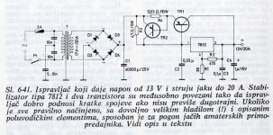
Here is the scan of the original schematic:
TRANSFORMER POWER~400W(PRIMARY)
SECONDARY =17 VOLTS/~20A
TR1=2N5302
TR2=BD136
The circuit has over current protection (from short circuit) if time interval is not too long!
FINALLY:
My recommendation is that you can add more parallel transistors in place of 2N5302(if you can't find this) with other equivalent replacement or for example:TIP2955 or similar but PNP type plus adding extra ceramic resistors of 0.1 Ohm/5watts on each emitter of the transistors which should be connected in place of TR1.
Author of this book also mentioned that we must put TR1 of a big heat sink and to use like upper side of the Box.
This is tested by many including myself and works.
So you must find other transformer or if you are able rewound the secondary to 17- 18 Volts.
I have rewind a lot's of transformers all types of cores even welded ones, and toroidal.
I wound my 2000VA toroidal core with naked hands end secondary wire I put is 2.4mm Cu lack diameter!
If I can help you more tell me how?
🙂
Attachments
Hidden somewhere, at a friend's house, I think I do have an 18v transformer. It's fairly hefty but I have no way of knowing what the VA rating is. It came out of a 100 watt sub woofer amplifier.
Also, I have noticed regulators using R1 and R2 to set the voltage. Was going to ask you about that.
Give me a day or two to hunt up that transformer and I'll get back to you.
Thanks again,
David
Also, I have noticed regulators using R1 and R2 to set the voltage. Was going to ask you about that.
Give me a day or two to hunt up that transformer and I'll get back to you.
Thanks again,
David
Also, I have noticed regulators using R1 and R2 to set the voltage. Was going to ask you about that.
With Adjustable regulators such as the LM317,the resistors are used to set the output voltage.
The same principal works for fixed regulators,such as the 7812. The output voltage is in relation to the ground pin on the regulator. So,if you 'lift' the ground pin above circuit ground,you can kind of trick the regulator into outputting a higher voltage,in relation to circuit ground.
Adding two diodes in the ground pin of the regulator will boost the output by approx ~1.4V (Diodes drop approx. ~0.7V each) up to ~13.4V
It's a kind of neat little trick to get different voltages from fixed regulators. 😉
davidlzimmer said:Also, I have noticed regulators using R1 and R2 to set the voltage. Was going to ask you about that.
Give me a day or two to hunt up that transformer and I'll get back to you.
Thanks again,
David [/B]
NO PROBLEM HAM BROTHER.
HERE FOR THOSE WHO ARE LAZY TO CALCULATE BY HAND(OLD SCHOOL) METHOD HERE IS THE SIMPLY STUPID METHOD TO CALCULATE VALUES OF THE VOLTAGE DIVIDER (RESISTORS R2/R1) USED IN MY ORIGINALLY PREVIOUSLY POSTED SCHEMATIC DIAGRAM FROM THE "Radio prirucnik za amatere i tehnicare Dr. Bozo Metzger(YU2BR)"-ONE OF THE BEST HAM BOOK, MY BIG RESPECT TO YU2BR.
VISIT THIS LINK AND JUST PUT VOLTAGE REFERENCE WHICH IN OUR CASE IS 12 VOLTS(LM7812), PUT THE (DESIRED OUTPUT VOLTAGE WHICH YOU WOULD LIKE TO HAVE @ OUTPUT), THAN PUT VALUE FOR R2 WHICH IS 470 OHM OR 0.47KOHM, AND THAN PRESS CALCULATE TO GET R1 VALUE.
IF YOU LIKE TO CHANGE THE PRESENT OUTPUT VOLTAGE WHICH NOW IS AROUND 13VDC, WITH ORIGINALLY POSTED VALUES FOR R1/R2, THAN PUT THE NEW DESIRED OUTPUT VOLTAGE (VO), FOR EXAMPLE 14 V AND LEAVE R2 VALUE LIKE IT IS=470 =0.47KOHM, AND PRESS CALCULATE TO GET VALUE FOR THE R1.
VERY EASY, ISN'T IT???
http://www.daycounter.com/Calculators/Voltage-Regulator-Resistor-Divider-Calculator.phtml
🙂 TELL ME IF I CAN FURTHER HELP YOU?
73 FROM Z37HWX
AND REMEMBER THAT OUR SPIRIT IS THE STRONGEST😎

Bad news. The transformer puts out 44v. Guess my memory is playing tricks on me. It has a center tapped secondary, so I can get 22v but, that would cut the current capability in half also.
Back to start again. Although, I might consider pulling some windings off, since I have no other use for this transformer.
The other two are too valuable as transformers for gain clones.
Regards,
David
Back to start again. Although, I might consider pulling some windings off, since I have no other use for this transformer.
The other two are too valuable as transformers for gain clones.
Regards,
David
You are wright.
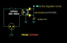
Try to find other 400 to 500w transformer with 18 volts secondary, or you can also use transformer with dual secondary like 2x 9(9-0-9) volts with BRIDGE RECTIFIER. with wire for about 20 A because you do not need more 20A.
ALSO YOU CAN USE 18-0-18 VOLTS TRANSFORMER WITH CENTER TAP BUT IN THIS CASE YOU MUST TO USE "COMMON CATHODE RECTIFIER" -TWO DIODES WITH CATHODE CONNECTED POINT" TO GET "+" VOLTAGE AND "-" VOLTAGE WILL BE THE CENTER TAP OF THE TRANSFORMER.
HERE IS THE SCHEMATIC: 🙂
Attachments
- Status
- Not open for further replies.
- Home
- Amplifiers
- Power Supplies
- Dummy transformer question